Hyundai Tucson: Power Relay (Type A)
Hyundai Tucson - Fourth generation (NX4) - (2020-2023) - Workshop Manual / Body Electrical System / Fuses And Relays / Power Relay (Type A)
Component Location
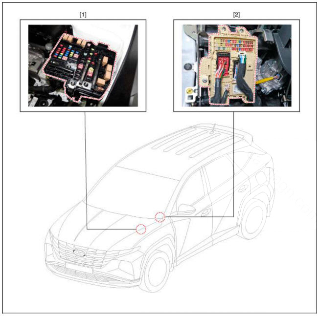
- Engine room junction block
- ICU Junction block
Inspection
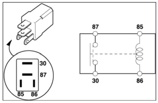
Power Relay (Type A)
- There should be continuity between the No.30 and No.87 terminals when power and ground are connected to the No.85 and No.86 terminals.
- There should be no continuity between the No.30 and No.87 terminals when power is disconnected.
Engine room relay box

Replacement of PCB Block
- Disconnect the negative (-) battery terminal.
- Push 4 hooks in the engine room relay box out to the arrow direction and put up the PCB block (A).
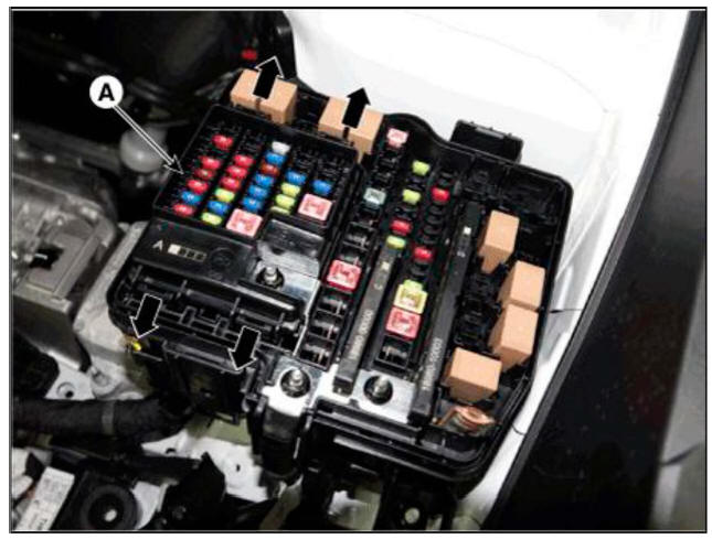
- Disconnect the connector and remove the the PCB block (A).
Fuse
- Be sure there is no play in the fuse holders, and that the fuses are held securely.
- Are the fuse capacities for each circuit correct?
- Are there any blown fuses?
- If a fuse is to be replaced, be sure to use a new fuse of the same capacity. Always determine why the fuse blew first and completely eliminate the problem before installing a new fuse.
Multi Fuse
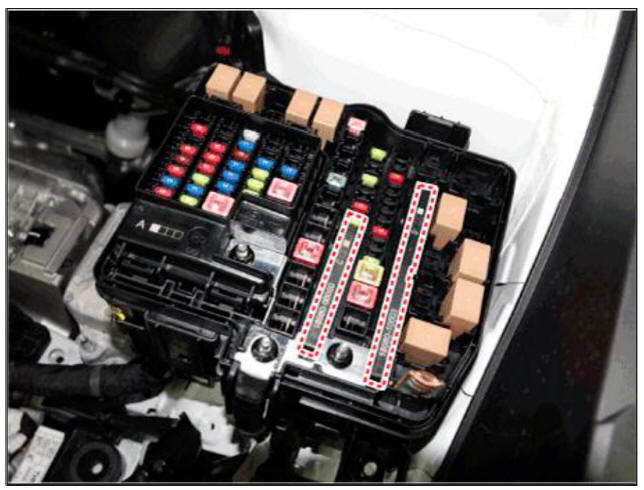
- Multi fuse (A) is needed to replace in the mass when it damaged only one fuse.
- Use the multi fuse capacities for each circuit correctly.
READ NEXT:
 ICU (Integrated Central Control Unit)
Dscription and Operation
ICU (Integrated Central Control Unit) is an integrated model of smart
junction block and central gateway.
It performs the function of conventional "Smart junction block" and the function
of communication med
Indicators And Gauges
Troubleshooting
Description
Cluster Variant Coding
As we have more options (SCC, VDC, EPB, Cubis, MDPS, TPMS. LDWS, ECS -) in
the car, the
dashboard now has more information to display depending on the chosen options.
For this reason, we
Power Door Locks
Front Door Lock Module Inspection
Inspection
Remove the front door trim.
(Refer to Body - "Front Door Trim")
Disconnect the connectors from the actuator.
Check actuator operation by connecting power and ground according to the
SEE MORE:
Parking Brake Adjustment
WARNING
After disassembling/assembling the caliper body or replacing the
caliper, parking brake cable or brake
disc, re-adjust the parking brake.
Remove the floor console assembly.
(Refer to Body - "Floor Console Assembly")
For
Forward/Reverse Parking Distance Warning (PDW)
Forward/Reverse Parking Distance
Warning will help warn the driver if an
obstacle is detected within a certain
distance when the vehicle is moving
forward or in reverse at low speeds.
Detecting sensor
[1] : Front ultrasonic sensors,
[2] :
Information
- Home
- Hyundai Tucson - Fourth generation (NX4) - (2020-2023) - Owner's Manual
- Hyundai Tucson - Fourth generation (NX4) - (2020-2023) - Workshop Manual
