Hyundai Tucson: General Information
Hyundai Tucson - Fourth generation (NX4) - (2020-2023) - Workshop Manual / Restraint / General Information
Please read the following precautions carefully before performing the airbag system service.
Observe the instructions described in this manual, or the airbags could accidentally deploy and cause damage or injuries.
- Except when performing electrical inspections, always turn the ignition switch OFF and disconnect the negative cable from the battery, and wait at least three minutes before beginning work.
WARNING
The contents in the memory are not erased even if the ignition switch is turned OFF or the battery cables are disconnected from the battery.
- Use the replacement parts which are manufactured to the same standards
as the original parts and
quality.
Do not install used SRS parts from another vehicle. Use only new parts when making SRS repairs.
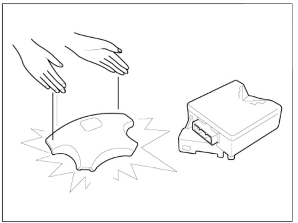
- Carefully inspect any SRS part before you install it. Do not install any part that shows signs of being dropped or improperly handled, such as dents, cracks or deformation.
- Before removing any of the SRSCM parts (including the disconnection of the connectors), always disconnect the SRSCM connector.
READ NEXT:
 Airbag Handling and Storage
Do not disassemble the airbags; it has no serviceable parts. Once an airbag
has been deployed, it cannot be repaired or reused.
For temporary storage of the air bag during sendee, please observe the following
precautions.
Store the removed
Wiring Precautions
SRS wiring can be identified by special yellow outer covering Observe the
instructions described in
this section.
Never attempt to modify, splice, or repair SRS wiring. If there is an
open or damage in SRS wiring,
replace the harness.
Warning Lamp
Activation
Warning Lamp Behavior after Ignition On
As soon as the operating voltage is applied to the SRSCM ignition input, the
SRSCM activates the
warning lamp for a LED lamp check.
The lamp shall turn on for 6 seconds during the initialization phase an
SEE MORE:
System Interface
Description
Rear Corner Radar is a system that measures the relative speed and distance
from the following vehicles by using two
electromagnetic wave radar sensors attached to the rear bumper, and detects any
vehicle within the blind spot zone
Compressor - Disassembly
Disassembly
Remove the front tire RH.
(Refer to Suspension System - "Wheel")
Loosen the drive belt.
(Refer to Engine Mechanical System - "Drive Belt")
Remove the clutch bolt (A) while holding the pulley with a clutch b
Information
- Home
- Hyundai Tucson - Fourth generation (NX4) - (2020-2023) - Owner's Manual
- Hyundai Tucson - Fourth generation (NX4) - (2020-2023) - Workshop Manual
