Hyundai Tucson: Warning Lamp Activation
Warning Lamp Behavior after Ignition On
As soon as the operating voltage is applied to the SRSCM ignition input, the SRSCM activates the warning lamp for a LED lamp check.
The lamp shall turn on for 6 seconds during the initialization phase and be aimed off afterward.
To alert the driver, the warning lamp shall turn on for 6 seconds and off for one second then on continuously after the operating voltage is applied if any active fault exists.
- Active fault.
- Normal or historical fault only exist.

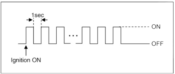
- When turning the ignition switch ON during variant coding (EOL) mode,
the airbag warning lamp
is turned on and blinks at intervals of 1 second till the coding is
completed.
If the variant coding is completed normally, the airbag warning lamp will turn on for 6 seconds, and then turned off. Otherwise the airbag warning lamp continuously blinks at intervals of 1 second.
(1) In case the variant coding is normally completed
(2) In case the variant coding is not completed
When there is active fault in airbag system or SRSCM internal fault, the variant coding (EOL) cannot be completed. In this case, perform the variant coding (EOL) procedure again after troubleshooting with the self-diagnosis device.
SRSCM Independent Warning Lamp Activation
There are certain fault conditions in which the SRSCM cannot function and thus cannot control the operation of the standard warning lamp. In these cases, the standard warning lamp is directly activated by appropriate circuitry that operates independently of the SRSCM. These cases are:
- Loss of battery supply to the SRSCM : warning lamp turned on continuously.
- Loss of internal operating voltage : warning lamp turned on continuously.
- Loss of Microprocessor operation : warning lamp turned on continuously.
- SRSCM not connected : warning lamp turned on continuously.
Specification
Special Service Tools
Tool (Number and Name)/ Illustration/ Use
Deployment tool
0957A-34100A/  / Airbag deployment
tool.
/ Airbag deployment
tool.
Use with (0957A-AL140, 0957A-AL160)
Dummy
095 7A-3 8200/  / Simulator to check
the
resistanceof each wiring
harness.
/ Simulator to check
the
resistanceof each wiring
harness.
Use with (095 7A-AL170, 0957A-AL190)
Airbag deployment
& dummy adapter
kit
0957A-AL100/ 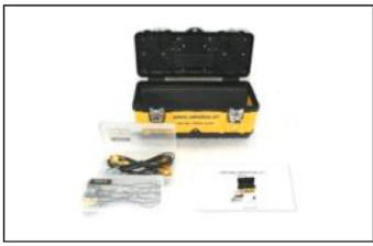 / Use with airbag
deployment and airbag
inspection.
/ Use with airbag
deployment and airbag
inspection.
Deployment adapter
0957A-AL120/ 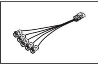 / Use with deployment
tool.
/ Use with deployment
tool.
(0957A-34100A) (SAB, CSAB)
Deployment adapter
0957A-AL140/  / Use with deployment
tool.
/ Use with deployment
tool.
(0957A-34100A) (DAB, PAB, CAB. BPT)
Dummy adapter
0957A-AL170/ 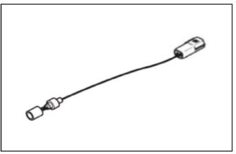 / Use with dummy.
(0957A-38200) (DAB.
PAB, CAB. CSAB. SAB.
BPT)
DAB : Driver Airbag
PAB : Passenger Airbag
SAB : Side Airbag
CAB : Curtain Airbag
BPT : Seat Belt Pretensioner
General Information
The supplemental restraint system (SRS) is designed to supplement the seat belt to help reduce the risk or severity of injury to the driver and passenger by activating and deploying the driver, passenger, side airbag and belt pretensioner in certain frontal or side collisions.
The SRS (Airbag) consists o f ; a driver side airbag module located in the center of the steering wheel, which contains the folded cushion and an inflator unit; a passenger side airbag module located in the passenger side crash pad contains the folded cushion assembled with inflator unit; side airbag modules located in the front seat contain the folded cushion and an inflator unit; curtain airbag modules located inside of the headliner which contains folded cushions and inflator units. The impact sensing function of the SRSCM is carried out by electronic accelerometer that continuously measure the vehicle's acceleration and delivers a corresponding signal through amplifying and filtering circuitry to the microprocessor.
SRSCM (SRS Control Module)
SRSCM will detect front impact with front impact sensors and internal acceleration sensors inside of SRSCM. For side impact, SRSCM will detect the side impact with 4 side impact sensors, 2 conventional acceleration sensors in Center pillar inner locations and 2 pressure sensing sensors in side of front door module, and internal acceleration sensor inside of SRSCM.
SRSCM is designed to issue corresponding airbag module(s) deployment(s) using above described sensor inputs.
- DC/DC converter: DC/DC converter in power supply unit includes up/down transformer converter, and provides ignition voltage for all firing circuits, implemented as ASICs and the internal operation voltage of the SRSCM itself, if the internal operation voltage is below critical value setting, it will perform resetting.
- Back up power supply : SRSCM has separate back up power supply, that will supply deployment energy instantly in low voltage condition or upon power failure by front crash.
- Self diagnosis : SRSCM will constantly monitor current SRS operation status and detect system failure while vehicle power supply is on, system failure may be checked with trouble codes using self-diagnosis.
- Airbag warning lamp on : Upon detecting error, the module will transmit
signal to SRSCM
indicator lamp located at cluster. MIL lamp will indicat to the driver that
there is an SRS error.
Upon ignition key on, SRS lamp will turn on for about six seconds.
- Trouble code registration : Upon error occurrence in system, SRSCM will store DTC corresponding to the error. DTC can be cleared only by self-diagnosis. However, if an internal fault code is active or if a crash is recorded the fault clearing cannot be performed.
- Self diagnostic connector : Data stored in SRSCM memory will be output to self-diagnosis or other external output devices through a connector located below driver side crash pad.
- Once airbag is deployed, SRSCM should not be used again but replaced.
- SRSCM will determine whether passenger fasten the seat belt by the signal from built-in switch in seat belt buckle, and deploy front seat airbag at each set crash speed.
- Side airbag deployment will be determined by SRSCM that will detect satellite sensor impact signal upon side crash, irrespective to seat belt condition.
READ NEXT:
 SRSCM
SRSCM
Components Location
Supplemental Restraint System Control Module (SRSC'M)
Gravity Side Impact Sensor (G-SIS) _ C pillar
Gravity Side Impact Sensor (G-SIS) _ B pillar
Front Impact Sensor (FIS) RH
Front Impact Sensor (FIS) LH
Pres
Supplemental Restraint System Control Module (SRSCM)
Components Location
Supplemental Restraint System Control Module (SRSCM)
Supplemental Restraint System Control Module (SRSCM)
Removal
Disconnect the battery negative terminal.
WARNING
After disconnecting the cables
SRSCM - Installation
Installation
Install in the reverse of the removal.
After installing the SRSCM, confirm proper system operation.
WARNING
SIf the Switch ON the ignition, the SRS indicator light should turn
on for about six seconds and then off.
Variant
SEE MORE:
Lane Keeping Assist Malfunction and Limitations
Lane Keeping Assist malfunction
When Lane Keeping Assist is not working
properly, the 'Check Lane Keeping Assist
(LKA) system' warning message will
appear and the yellow indicator
light will illuminate on the cluster. If this
occurs, have
Electric WGT Control Actuator- Installation
WARNING
When replacing the Electric WGT Control Actuator, perform the
rod adjustment procedure.
When install the electric WGT control actuator, do not reuse a
C-Ring.
Install in the reverse order of removal.
Adjustment
Rod Adjus
Information
- Home
- Hyundai Tucson - Fourth generation (NX4) - (2020-2023) - Owner's Manual
- Hyundai Tucson - Fourth generation (NX4) - (2020-2023) - Workshop Manual
