Hyundai Tucson: Electronic Parking Brake (EPB)
Hyundai Tucson - Fourth generation (NX4) - (2020-2023) - Workshop Manual / Brake System / Parking Brake System / Electronic Parking Brake (EPB)
Components
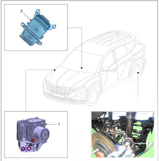
- ESC Control Module (HECU)
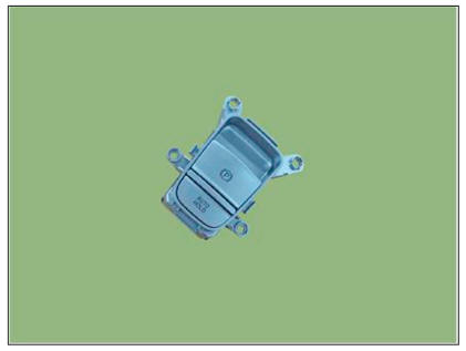
- EPB Switch
- Electronic Parking Brake (EPB) actuator
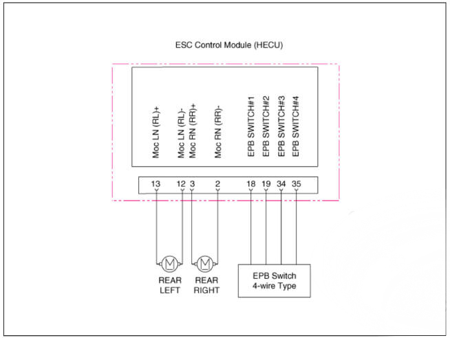
Circuit Diagram
Electronic Parking Brake (EPB)- Removal
WARNING
Be careful not to damage the parts located under the vehicle (floor under cover, fuel filter, fuel tank and canister) when raising the vehicle using the lift.
(Refer to General Information - "Lift and Support Points")
EPB Switch
- Turn ignition switch off and disconnect the battery (-) cable from the battery.
- Remove the floor console upper cover.
Refer to Body - "Floor Console Assembly"
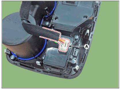
- Disconnect the EPB switch connector (A).
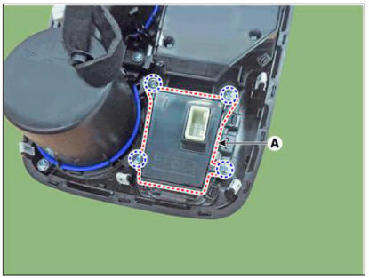
- Remove the EPB switch (A) after loosening the screw.
- Remove the EPB actuator from rear caliper.
(Refer to Brake System - "Rear Disc Brake")
Electronic Parking Brake (EPB)- Installation
- Install in the reverse order of removal.
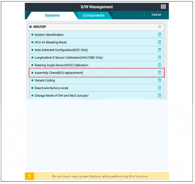
- After replacing the EPB actuator, make sure that the caliper is installed correctly by performing "Check assembling (ECU replaced)" from the option
READ NEXT:
 Description of ESP
Electronic Stability Control (ESC) recognizes critical driving conditions,
such as panic reactions in dangerous situations, and
stabilizes the vehicle by individual wheel braking and engine control input.
ESC adds an additional function known a
Warning Lamp Control( ABS/EBD)
Warning Lamp Control
ABS Warning Lamp module
The active ABS warning lamp module indicates the self-test and failure status
of the ABS. The ABS warning lamp shall be on :
During the initialization phase after IGN ON. (continuously 3 second
SEE MORE:
Ignition Lock & Clutch Switch - Description
Description
Clutch operation is detected through clutch switch signal. This signal
enables ECM to cope with
instant change of load condition.
Clutch switch signal is used to detect engaged gear with vehicle speed
and engine speed.
Co
Multi Air Mode
Multi Air Mode (if equipped)
When the Multi-Air mode button is
pressed, air flow is directed to the
face level and floor level and through
perforated sections along the instrument
panel for the driver and passenger. The
multi-air mode L
Information
- Home
- Hyundai Tucson - Fourth generation (NX4) - (2020-2023) - Owner's Manual
- Hyundai Tucson - Fourth generation (NX4) - (2020-2023) - Workshop Manual
