Hyundai Tucson: Description of ESP
Electronic Stability Control (ESC) recognizes critical driving conditions, such as panic reactions in dangerous situations, and stabilizes the vehicle by individual wheel braking and engine control input.
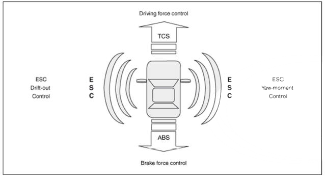
ESC adds an additional function known as Active Yaw Control (AYC) to the ABS, TCS, EBD and ESC functions. On contrary, the ABS/TCS function controls wheel slip during braking and accelerating, and thus, mainly intervenes in the longitudinal dynamics of the vehicle, and the active yaw control stabilizes the vehicle on the vertical axis.
This is achieved by individual wheel brake intervention and adaptation of momentary engine torque with no need for any action to be taken by the driver.
ESC essentially consists of three assemblies : the sensors, the electronic control unit and the acmators.
The stability control feature works under all driving and operating conditions. Under certain driving conditions, the ABS/TCS function can be activated simultaneously with the ESC function in response to a command by the driver.
In the event of a failure of the stability control function, the basic safety function, ABS, is still maintained.
Description of ESP Control
ESC system consists of ABS/EBD. TCS and AYC functions.
ABS/EBD function : The ECU changes the active sensor signal (current shift) coming from the four wheel sensors into square waves. By using the input of above signals, the ECU calculates the vehicle speed and the acceleration & deceleration of the four wheels. And. the ECU determines whether the ABS/EBD should be actuated or not.
TCS function prevents the wheel slip of drive direction by adding the brake pressure and engine torque reduction via CAN communication. TCS function uses the wheel speed sensor signal to determine the wheel slip as far as ABS function.
AYC function prevents unstable maneuver of the vehicle. To determine the vehicle maneuver, AYC function uses the maneuver sensor signals (Yaw Rate Sensor, Lateral Acceleration Sensor, and Steering Wheel Angle Sensor).
If vehicle maneuver is unstable (Over Steer or Under Steer). AYC function applies the brake pressure on certain wheel, and sends engine torque reduction signal by CAN.
After the ignition on. the ECU continuously diagnoses the system for failures (self-diagnosis). If a system failure is detected, the ECU informs driver of the system failure through the BRAKE ABS/ESC warning lamp (fail-safe warning).
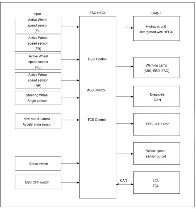
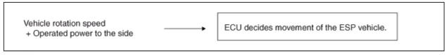
Input and Output Diagram
ESC Operation Mode
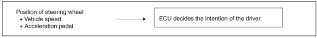
- STEP 1
The ESC analyzes the intention of the driver.
- STEP 2
It analyzes the movement of the ESC vehicle.
- STEP 3
The HEC'U calculates the required strategy, then actuates the appropriate
valves and sents torque control requests via CAN to
maintain vehicle stability. 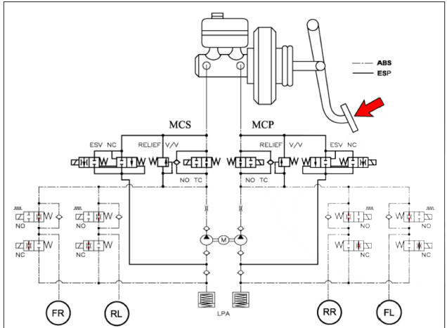
ESC Hydraulic System Diagram
- ESC Non-operation : Normal braking.
- ESC operation
READ NEXT:
 Warning Lamp Control( ABS/EBD)
Warning Lamp Control
ABS Warning Lamp module
The active ABS warning lamp module indicates the self-test and failure status
of the ABS. The ABS warning lamp shall be on :
During the initialization phase after IGN ON. (continuously 3 second
Electronic Stability Control System- Components
ESC Control unit (HECU)
Front wheel speed sensor
Rear wheel speed sensor
ABS warning lamp
Parking brake / EBD
Failure
Diagnosis
In principle, ESC and TCS controls are prohibited in case of ABS
failure.
When ESC or TCS fail
ABS Does Not Operate/ ABS Does Not Operate (Intermittently)
ABS Does Not Operate
Detecting condition
Brake operation varies depending on driving conditions and road surface
conditions, so diagnosis can be difficult. However if a normal DTC is
displayed, check the following probable cause. When the problem
SEE MORE:
Parking Distance Warning (PDW)
Description
PDW consists of 8 sensors (front: 4 units, rear : 4 units) that are used
to detect obstacles and transmit the result in three
separate warning levels, the first, second and third to IBU via LIN
communication.
IBU decides the
Differential Carrier Assembly - Reassembly
Reassembly
Pinion drive gear assembly
Install the inner pinion bearing adjustment shim (A) 011 the pinion
drive gear assembly.
Install the inner pinion bearing (A) on the pinion drive gear using SST
(0K530-P2200) and press.
Information
- Home
- Hyundai Tucson - Fourth generation (NX4) - (2020-2023) - Owner's Manual
- Hyundai Tucson - Fourth generation (NX4) - (2020-2023) - Workshop Manual
