Hyundai Tucson: Connector assembly status test- Troubleshooting
Hyundai Tucson - Fourth generation (NX4) - (2020-2023) - Workshop Manual / Engine Electrical System / Ignition System / Connector assembly status test- Troubleshooting
Connector assembly status test
- Disconnect the ignition coil connectors (A) and reinstall it.

Test for changing position of each ignition coil
- Ignition coil w/ misfire code
- Ignition coil w/o misfire code
WARNING
Do not move with spark plug at the same time (move the ignition coil
only) 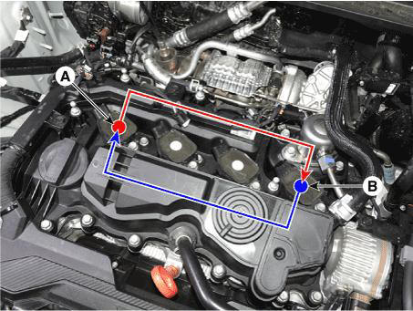
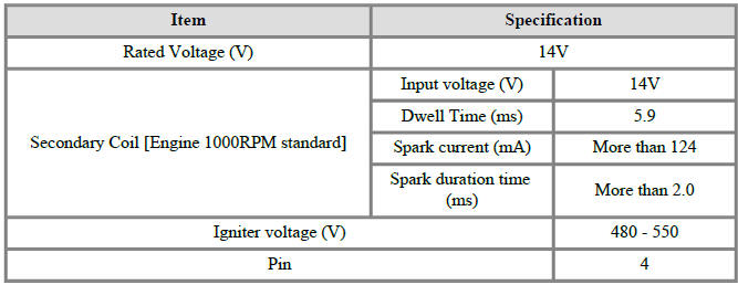
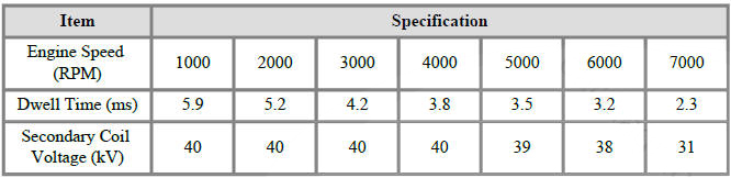
Specification
Circuit Diagram
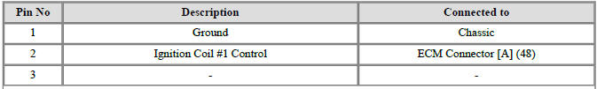
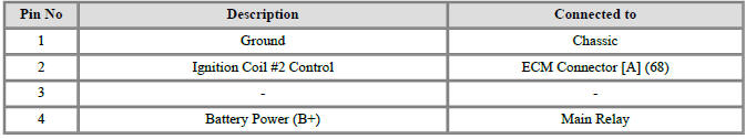
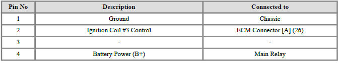
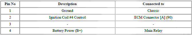
Ignition Coil Connector Terminal Function
Ignition Coil Terminal Function
* Connected to number
Ignition Coil #1 (Cylinder #1)

Ignition Coil #2 (Cylinder #2)
Ignition Coil #3 (Cylinder #3)
Ignition Coil #4 (Cylinder #4)
READ NEXT:
 Engine Cover
Removal
Turn the ignition switch OFF and disconnect the battery (-) terminal.
Remove the engine cover.
(Refer to Engine Mechanical System - "Engine Cover")
Disconnect the ignition coil connectors (A).
WARNING
When remov
On vehicle inspection
Inspection
Accelerate the engine to about 3,000 rpm 3 times or more.
Remove the spark plug.
(Refer to Spark Plug - "Removal")
Check the spark plug visually.
If the electrode is dry, the spark plug is normal.
If the
Specifications
Service Data
Ignition System
Ignition Coil
Spark plug
Charging System
Battery
CMF60L-DIN
Model type description
Cold Cranking Ampere (CCA) : A rating used in the battery industry to define
a battery's ability
to start a
SEE MORE:
Where are the air bags?
Driver's and passenger's front air
bags
Driver's front air bag
Passenger's front air bag
Your vehicle is equipped with a
Supplemental Restraint System (SRS)
and lap/shoulder belts at both the driver
and passenger seating positions.
Automatic Stop Operation Check
Operate the motor at low speed using the stalk control.
Stop the motor operation anywhere except at the off position by
disconnecting terminal 3.
Connect the positive (+) lead from the battery to terminal 3 and the
negative (-) lead to t
Information
- Home
- Hyundai Tucson - Fourth generation (NX4) - (2020-2023) - Owner's Manual
- Hyundai Tucson - Fourth generation (NX4) - (2020-2023) - Workshop Manual
