Hyundai Tucson: Camshaft - Installation
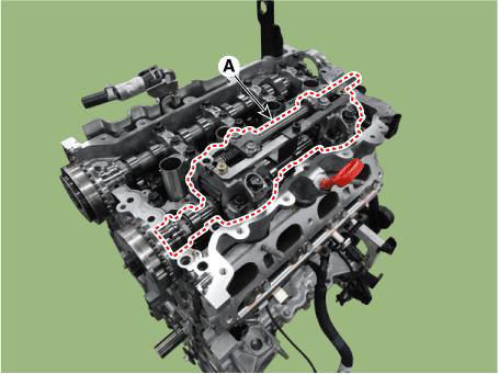
- Install the intake CVVT (A).
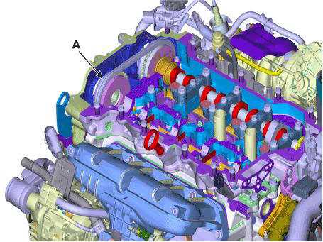
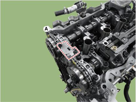
- Install the CVVD assembly (A).
WARNING
- After installing the CVVD, check whether the swing arm is separated or is installed correctly.
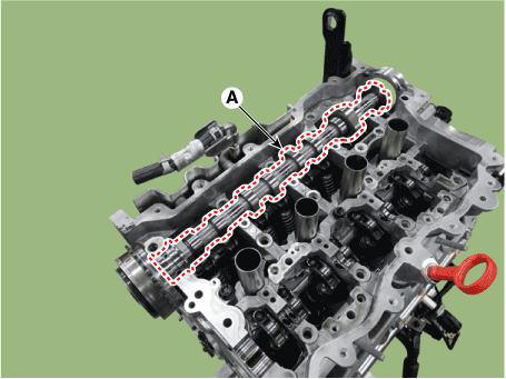
- When installing the intake camshaft, spray the engine oil to
the camshaft journal installing part (A) of the
cam carrier.
The amount of application should be enough to flow down both the front and back sides when it is applied to the center.
- For installation, the timing mark (A) of the intake CVVT and
the timing chain mark (B) should be matched

WARNING
- During the installation, there should be no artifical rotation or movement of the guide bracket and control shaft.
- When removing the CVVD fixing jig, be sure to securely tighten the M6 bolts.
- If CVVD fixing jig is available, be sure to work by using it.
When Using the CVVD fixture
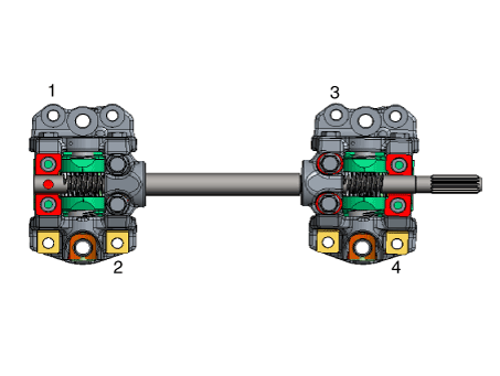
- When installing the CVVD assembly mounting bolts (M6), tighten sequence shown.
Tightening torque :
1ST
4.9 - 6.9 N.m (0.5 - 0.7 kgf.m, 3.6 - 5.1 lb-ft)
2nd
9.8 - 11.8 N.m (1.0 - 1.2 kgf.m, 7.2 - 8.7 lb-ft)
- Remove the CVVD fixture (A).
- Provisionally tighten the CVVD assembly mounting bolts (M8) in sequence shown below.
Tightening torque : 9.8 - 11.8 N.m (1.0 - 1.2 kgf.m, 7.2 - 8.7 lb-ft)

- Remove the CVVD assembly mounting bolts (M6) (A).
- Provisionally tighten the CVVD assembly mounting bolts (M6) in sequence shown below.
Tightening torque : 4.9 - 6.9 N.m (0.5 - 0.7 kgf.m, 3.6 - 5.1 lb-ft)

- Tighten the CVVD assembly mounting bolts (M8) in sequence shown below.
Tightening torque : 18.6 - 22.6 N.m (1.9 - 2.3 kgf.m, 13.7 - 16.6 lb-ft)
- Tighten the CVVD assembly mounting bolts (M6) in sequence shown below.
Tightening torque : 9.8 - 11.8 N.m (1.0 - 1.2 kgf.m, 7.2 - 8.7 lb-ft)

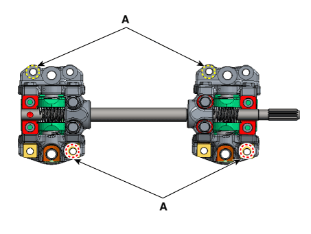
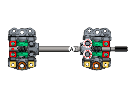
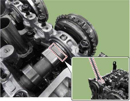
- Measure the clearance between the control shaft bearing cap and the end of control shaft using a clearance gauge.
Clearance : 0.0 - 0.05 mm (0.0 - 0.002 in.)
When not using the CVVD fixture
- Provisionally tighten the CVVD assembly mounting bolts (M6) in sequence shown below
Tightening torque : 4.9 - 6.9 N.m (0.5 - 0.7 kgf.m, 3.6 - 5.1 lb-ft)

- Provisionally tighten the CVVD assembly mounting bolts (M8) in sequence shown below.
Tightening torque : 9.8 - 11.8 N.m (1.0 - 1.2 kgf.m, 7.2 - 8.7 lb-ft)
- Tighten the CVVD assembly mounting bolts (M8) in sequence shown below.
Tightening torque : 18.6 - 22.6 N.m (1.9 - 2.3 kgf.m, 13.7 - 16.6 lb-ft)

- Tighten the CVVD assembly mounting bolts (M6) in sequence shown below.
Tightening torque : 9.8 - 11.8 N.m (1.0 - 1.2 kgf.m, 7.2 - 8.7 lb-ft)

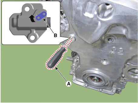
- Release the torque of control shaft bearing cap bolt (A).
- Push the control shaft bearing cap as close as possible in the direction of the arrow
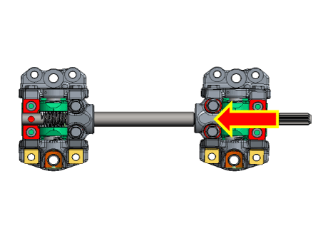
- Install the control shaft bearing cap mounting bolts (A).
Tightening torque : 9.8 - 11.8 N.m (1.0 - 1.2 kgf.m, 7.2 - 8.7 lb-ft)

- Measure the clearance between the control shaft bearing cap and the end of control shaft using a clearance gauge.
Clearance : 0.0 - 0.05 mm (0.0 - 0.002 in.)

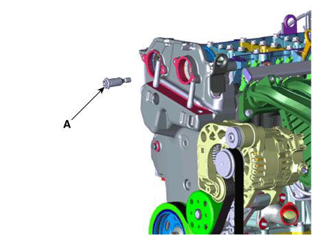
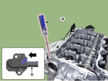
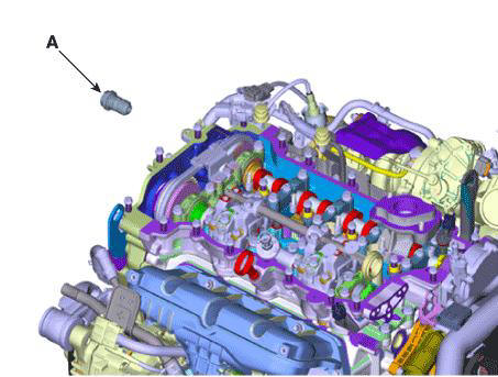
- Install the intake OCV & center bolt (A).
Tightening torque : 22.6 - 26.5 N.m (2.3 - 2.7 kgf.m, 16.6 - 19.5 lb-ft) + 32 - 36º
WARNING
- To prevent impurities from entering intake oil control valve (OCV) & center bolt, wear rubber gloves.
- intake oil control valve (OCV) and center bolt, hold the
hexagonal portion on the camshaft with a wrench to
prevent the camshaft from rotating.
- Compress the timing chain tensioner piston.
(1) With a pry bar (A), compress the timing chain tensioner piston (B).
(2) With a thin gimlet (A), raise the ratchet plate (B) of the timing chain tensioner and fix the piston.
WARNING
Do not remove the pick (A).
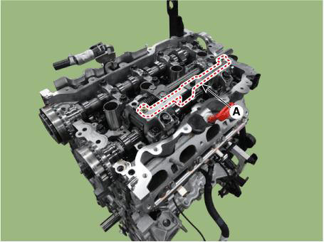
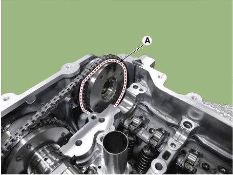
- Install the exhaust CVVT (A).
WARNING
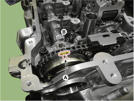
When installing the timing chain, be sure that the timing mark (A) of each sprocket is matched with the timing mark (B) (color link) of the timing chain.
Exhaust CVVT Timing Mark
- Install the exhaust camshaft (A).
WARNING
- After installing exhaust camshaft, check whether the swing arm is separated or is installed correctly.
- When installing the exhaust camshaft, spray the engine oil to
the camshaft journal installing part of the cam
carrier.
The amount of application should be enough to flow down both the front and back sides when it is applied to the center..
- Install the exhaust oil control valve (OCV) and center bolt (A).
Tightening torque : 22.6 - 26.5 N.m (2.3 - 2.7 kgf.m, 16.6 - 19.5 lb-ft) + 32 - 36º
WARNING
- To prevent impurities from entering exhaust oil control valve (OCV) & center bolt, wear rubber gloves.
- When installing the exhaust oil control valve (OCV) and center
bolt, hold the hexagonal portion on the
camshaft with a wrench to prevent the camshaft from rotating.
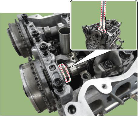
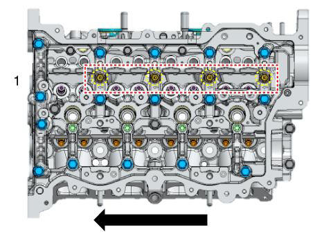
- Install the camshaft front bearing cap (A) and camshaft bearing caps (B).

WARNING
- If there is enough engine oil on the camshaft front bearing cap and camshaft bearing cap installing bolt and bolt hole, tighten to the minimum required tightening torque.
- Apply engine oil the upper part of the intake / exhaust camshaft journal, then install the camshaft front bearing cap and camshaft bearing cap. The amount of application should be enough to flow down both the front and back sides when it is applied to the center.
1) Install the camshaft front bearing cap and camshaft bearing cap installing bolt with direction from back of engine to the front of engine according to the procedure at down below.
Tightening torque : 4.9 - 6.9 N.m (0.5 - 0.7 kgf.m, 3.6 - 5.1 lb-ft)

2) Install the camshaft bearing cap installing bolt with direction from back of engine to the front of engine according to the procedure at down below.
Tightening torque : 4.9 - 6.9 N.m (0.5 - 0.7 kgf.m, 3.6 - 5.1 lb-ft)
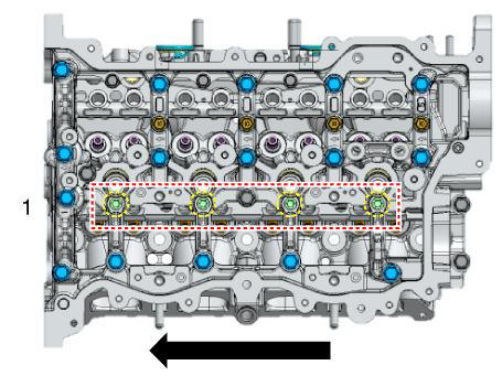
3) Install the camshaft bearing cap installing bolt with direction from back of engine to the front of engine according to the procedure at down below.
Tightening torque : 4.9 - 6.9 N.m (0.5 - 0.7 kgf.m, 3.6 - 5.1 lb-ft)

4) Install the camshaft front bearing cap and camshaft bearing cap installing bolt with direction from back of engine to the front of engine according to the procedure at down below.
Tightening torque : 9.8 - 11.8 N.m (1.0 - 1.2 kgf.m, 7.2 - 8.7 lb-ft)
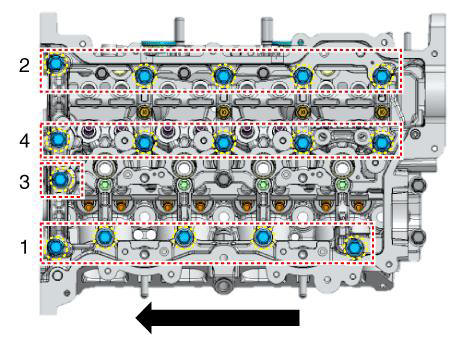
5) Install the camshaft front bearing cap and camshaft bearing cap installing bolt with direction from back of engine to the front of engine according to the procedure at down below.
Tightening torque : 18.6 - 22.6 N.m (1.9 - 2.3 kgf.m, 13.7 - 16.6 lb-ft)

6) Install the camshaft bearing cap installing bolt with direction from back of engine to the front of engine according to the procedure at down below.
Tightening torque : 11.8 - 13.7 N.m (1.2 - 1.4 kgf.m, 8.7 - 10.1 lb-ft)

7) Install the camshaft bearing cap installing bolt with direction from back of engine to the front of engine according to the procedure at down below.
Tightening torque : 11.8 - 13.7 N.m (1.2 - 1.4 kgf.m, 8.7 - 10.1 lb-ft)
- Remove the fine gimlets (A) that hold the timing chain tensioner.

- When installing the timing chain, be sure that the timing mark (A) of each sprocket is matched with the timing mark (B) (color link) of the timing chain.
Intake CVVT Timing Mark
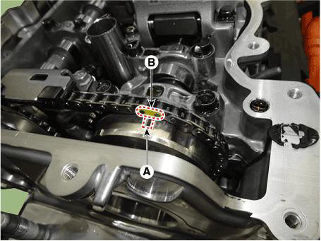
Exhaust CVVT Timing Mark

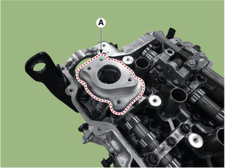
- Install the fuel pump bracket (A).
Tightening torque : 18.6 - 23.5 N.m (1.9 - 2.4 kgf.m, 13.7 - 17.4 lb-ft)
- Install the cam to cam guide (A).
Tightening torque : 9.8 - 11.8 N.m (1.0 - 1.2 kgf.m, 7.2 - 8.7 lb-ft)
- Install the intake and exhaust variable force solenoid (VFS) valves (A).
Tightening torque : 9.8 - 11.8 N.m (1.0 - 1.2 kgf.m, 7.2 - 8.7 lb-ft)

- Install the cylinder head cover.
(Refer to Cylinder Head Assembly - "Cylinder Head Cover")
READ NEXT:
 Camshaft - Description
CVVD (Continuous Variable Valve Duration) System is a device to control the
optimum open and close timing according to
the driving mode by changing the valve opening section.
It is composed of cam shaft, CVVD assembly, and CVVD acatuator.
Th
When not using the CVVD fixture
(3) Remove the CVVD assembly.
Remove the Intake CVVT (A).
Installation
Install the Intake CVVT (A).
Install the CVVD assembly (A).
WARNING
After installing the CVVD, check whether the swing arm is
separated
When Using the CVVD fixture
When installing the CVVD assembly mounting bolts (M6), tighten sequence
shown.
Tightening torque :
1ST
4.9 - 6.9 N.m (0.5 - 0.7 kgf.m, 3.6 - 5.1 lb-ft)
2nd
9.8 - 11.8 N.m (1.0 - 1.2 kgf.m, 7.2 - 8.7 lb-ft)
Remove the CVVD fixture
SEE MORE:
Glass Adjustment
WARNING
Check the glass run channel for damage or deterioration, and replace
it if necessary.
Remove the front door trim.
(Refer to Front Door - "Front Door Trim")
Lower the glass by operating the power window switch until the gl
Engine Mechanical System - Installation
Installation
Install in the reverse order of removal.
Disassembly
Remove the M-terminal nut (A) on the magnetic switch assembly (B).
After loosening the screws (A), remove the magnetic switch assembly.
Remove the throug
Information
- Home
- Hyundai Tucson - Fourth generation (NX4) - (2020-2023) - Owner's Manual
- Hyundai Tucson - Fourth generation (NX4) - (2020-2023) - Workshop Manual
