Hyundai Tucson: Brake Pedal
Components
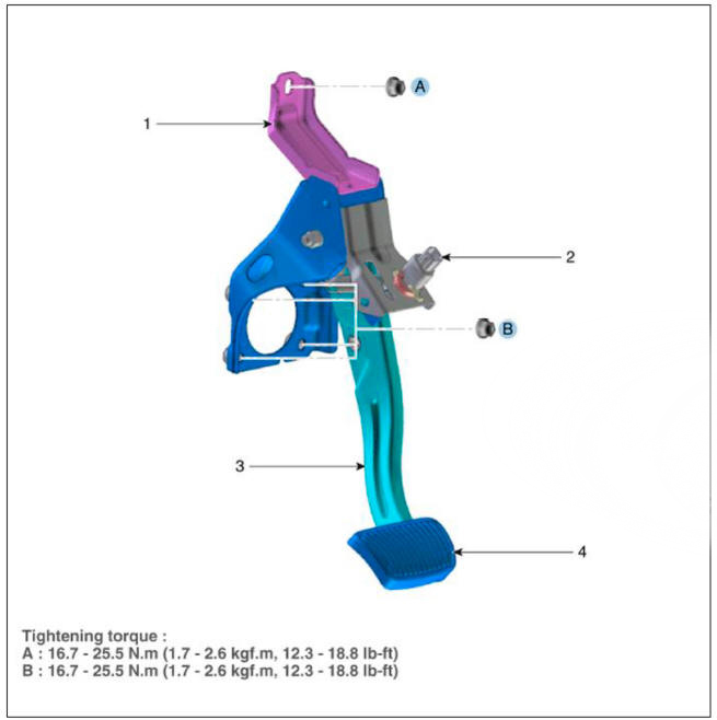
- Brake member assembly
- Stop lamp switch
- Brake pedal arm assembly
- Brake pedal pad
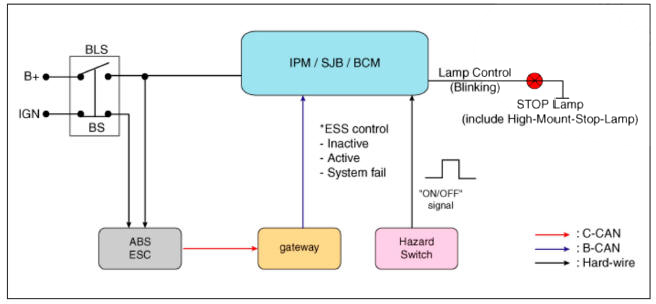
Schematic Diagram
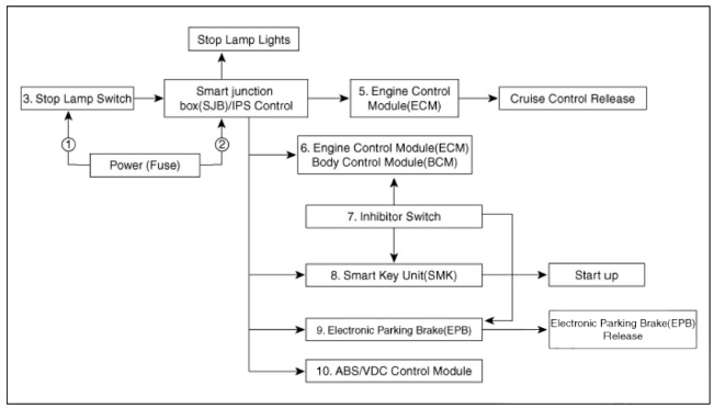
System circuit diagram
Terminal Function

Adjustment
- Turn ignition switch OFF and disconnect the negative (-) batteiy cable.
- Remove the crash pad lower panel.
(Refer to Body - "Crash Pad Lower Panel")
- Confirm the gap between stop lamp switch and bracket.
Stop lamp clearance (A) : 1.0 - 2.0 mm (0.04 - 0.08 in.)
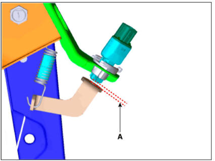
- If the gap between stop lamp switch and bracket is not 1.0 - 2.0 mm (0.04 - 0.08 in), check the mounting clip and other part of around stop lamp.
- If there is normal, remove the stop lamp switch and then install again.
Inspection
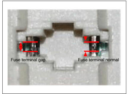
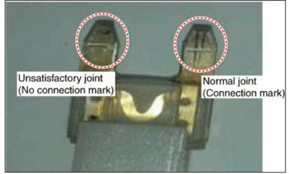
- Fuse inspection
Mount the test fuse to the switch fuse and relay fuse part to confirm a normal joint fit.
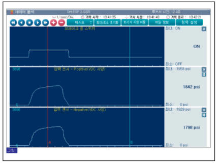
- Diagnostic tool Data Analysis
- Analyze diagnostic tool data and confirm if there is anything wrong with the stop lamp switch.
(1) Connect the diagnostic tool to the self-diagnosis connector.
(2) Turn the spark switch on (3) Step on the brake pedal.
(4) Inspect the "brake switch" categoiy that displays the "sensor data" diagnostic tool.
Normal waveform : The pressure sensor signal value will change according to the brake ON/OFF switch.
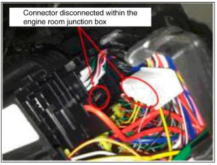
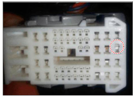
- Inspection of connector by each part
Check to see whether or not each connector has been damaged, or terminal surge, or incomplete connection has taken place
Engine room junction box
ABS/VDC control module
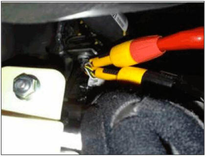
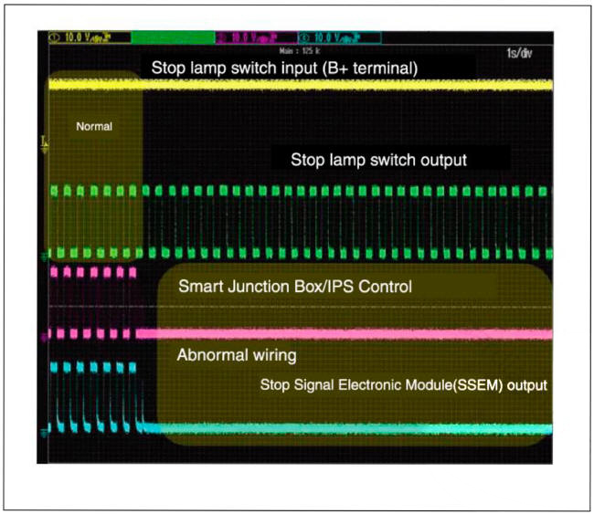
- Inspect the stop lamp circuit
Connect probe to each terminal wire and confirm oscilloscope waveform.
Stop lamp switch input/output
Oscilloscope waveform screen
READ NEXT:
 Brake Pedal - Removal
Turn ignition switch OFF and disconnect the negative (-) batteiy cable.
Remove the crash pad lower panel.
(Refer to Body - "Crash Pad Lower Panel")
Disconnect the stop lamp switch connector (A).
Pull the locking plate (A)
Parking Brake System
Components
Lever Type
Parking brake pedal assembly
Equalizer assembly
Parking brake cable
Pedal Type
Parking brake pedal assembly
Front parking brake cable
Equalizer assembly
Rear parking brake cable
Removal
Disconnec
Parking Brake Pedal Stroke
Adjustment
WARNING
After disassembling/assembling the caliper body or replacing the
caliper, parking brake cable or brake
disc, re-adjust the parking brake.
To fit the cable, follow one of these procedures.
Apply a parking brake fully
SEE MORE:
DCT (Dual Clutch Transmission) System (SBW)
Troubleshooting
Specifications
Clutch Actuator
Gear Actuator
Inhibitor Switch
Type: Combination of output signals from 4 terminals
Specifications
Input speed sensor
Tightening Torques
Lubricants
IMT System Actuator
Components and Components Location
IMT system actuator
Connector and Terminal Information
Circuit Diagram
Information
- Home
- Hyundai Tucson - Fourth generation (NX4) - (2020-2023) - Owner's Manual
- Hyundai Tucson - Fourth generation (NX4) - (2020-2023) - Workshop Manual
