Hyundai Tucson: Brake Booster Operating
Hyundai Tucson - Fourth generation (NX4) - (2020-2023) - Workshop Manual / Brake System / Braking System - operation and description / Brake Booster Operating
Components
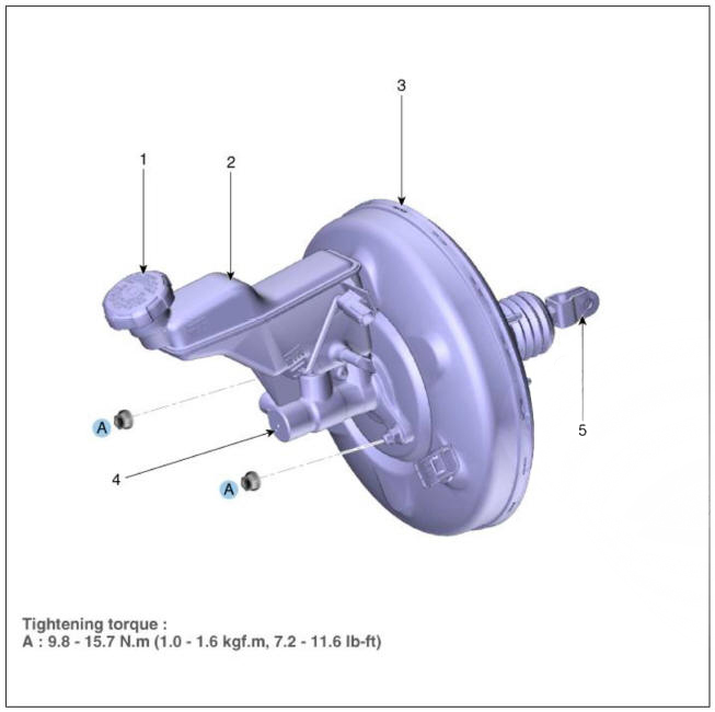
- Reservoir cap
- Reservoir
- Brake booster
- Master cylinder
- Push rod
Test
- Run the engine for one or two minutes, and then stop it. If the pedal depresses fully the first time but gradually becomes higher when depressed succeeding times, the booster is operating properly, if the pedal height remains unchanged, the booster is inoperative.
- With the engine stopped, step on the brake pedal several times.
Then step on the brake pedal and start the engine. If the pedal moves downward slightly, the booster is in good condition. If there is no change, the booster is inoperative.
- With the engine running, step on the brake pedal and then stop the engine.Hold the pedal depressed for 30 seconds. If the pedal height does not change, the booster is in good condition, if the pedal rises, the booster is inoperative.
If the above three tests are okay, the booster performance can be determined as good.
Even if one of the above three tests is not okay, check the check valve, vacuum hose and booster for malfunction.
Removal
- Turn ignition switch OFF and disconnect the negative (-) battery cable.
- Remove the battery and battery tray.
(Refer to Engine Electrical System - "Battery")
- Remove the air duct and air cleaner assembly.
(Refer to Intake and Exhaust System - "Air Cleaner")
- Remove the master cylinder.
(Refer to Brake System - "Master Cylinder")
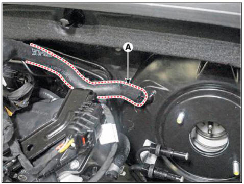
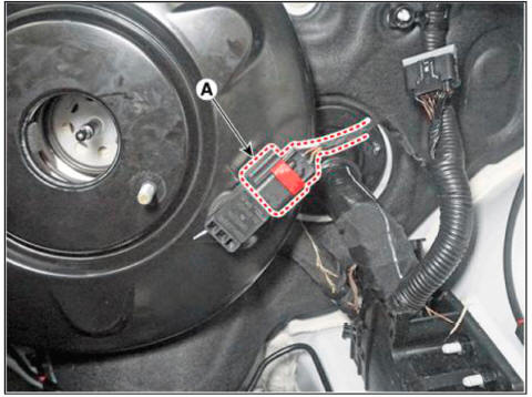
- Remove the fixing clip and the vacuum hose (A) from the brake booster.
- Disconnect the brake booster vacuum pressure sensor connector (A).
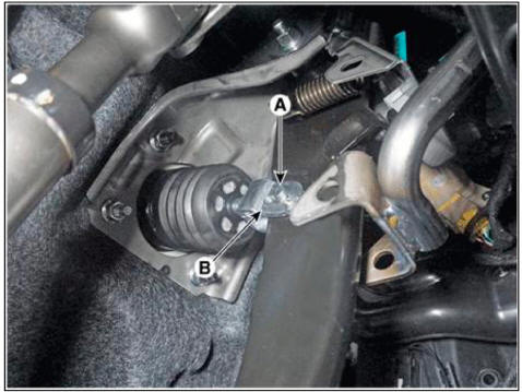
- Remove the snap pin (B) and the clevis pin (A).
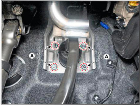
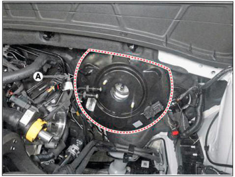
- Remove the brake booster (B) after loosening the mounting nuts (A).
Tightening torque : 16.7 - 25.5 N.m (1.7 - 2.6 kgf.m, 12.3 - 18.8 lb-ft)
Inspection
- Inspect the vacuum hose.
- Check the boot for damage.
Installation
- Installation is the reverse of removal.
WARNING
- Before installing the pin. apply the grease to the joint pin.
- Use a new snap pin whenever installing.
- After installation, bleed the brake system.
(Refer to Brake System - "Brake Bleeding Procedures")
- Check the brake oil leakage and pedal operating condition.
READ NEXT:
 Brake Booster - Removal
Components
Reservoir cap
Reservoir
Brake booster
Master cylinder
Push rod
Removal
Turm ignition switch OFF and disconnect the negative (-) battery cable.
Remove the battery.
(Refer to Engine Electrical System - "Batter
Brake Tube Engine Room
Components
Removal
WARNING
Be careful not to damage the parts located under the vehicle
(floor under cover, fuel filter, fuel tank and
canister) when raising the vehicle using the lift.
(Refer to General Information - "Lift and Su
Brake Tube- Replacement
Replacement
WARNING
Be careful not to damage the parts located under the vehicle (floor
under cover, fuel filter, fuel
tank and canister) when raising the vehicle using the lift.
(Refer to General Information - "Lift and Support Points&q
SEE MORE:
Power liftgate
The power liftgate open/close button
automatically opens and closes the
liftgate.
Before using the power liftgate
The power liftgate operates when the
gear is in P (Park) with the Engine Start/
Stop button in the ON position. However,
the lift
Rear shock absorber
Components
Lock nut
Insulator assembly
Dust cover
Rear shock absorber
Removal
WARNING
When lifting a vehicle using a lift, be careful not to damage the
lower parts of the vehicle (floor under
cover, fuel filter, fuel tank, canis
Information
- Home
- Hyundai Tucson - Fourth generation (NX4) - (2020-2023) - Owner's Manual
- Hyundai Tucson - Fourth generation (NX4) - (2020-2023) - Workshop Manual
