Hyundai Tucson: BMS ECU Terminal and Input/Output Signal
Terminal Function
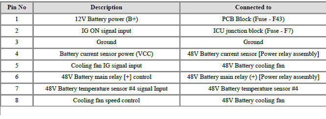
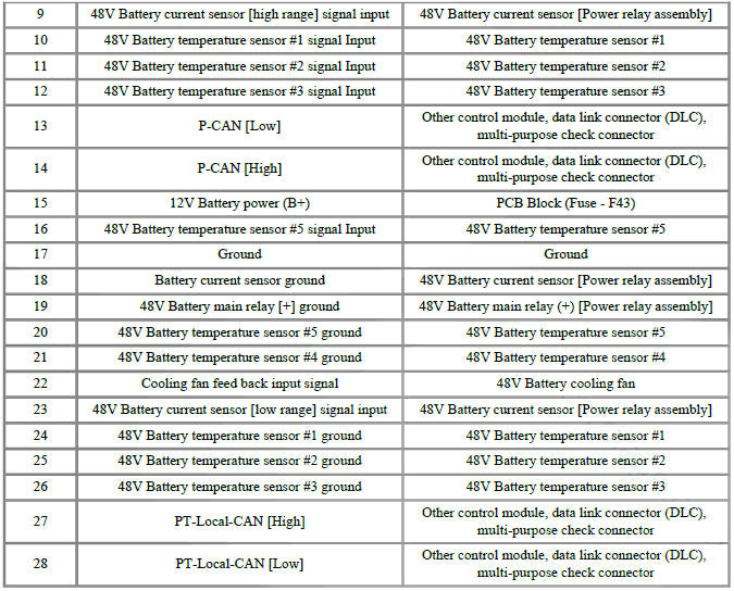
Connector B10-A
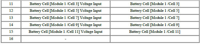
Connector B01-B

Removal
- Turn ignition switch OFF and disconnect the battery (-) terminal.
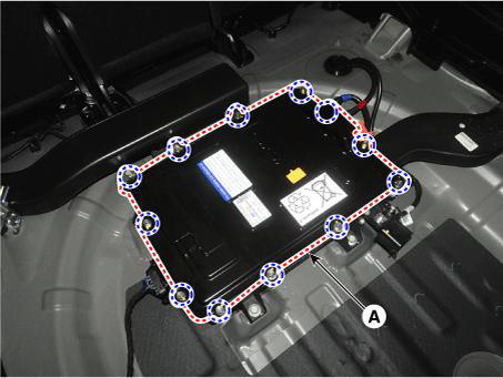
- Remove the 48V battery assembly.
(Refer to 48V Battery System - "Repair procedures")
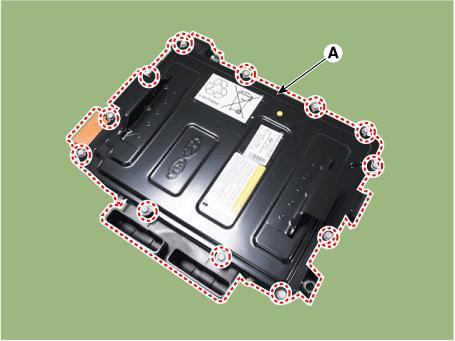
- Remove the battery cover (A) after loosening the mounting bolts.
Tightening torque : 7.8 - 11.8 N.m (0.8 - 1.2 kgf.m, 5.8 - 8.7 lb-ft)
- Remove the terminal capacitor (A) after loosening the mounting bolts.
Tightening torque : 7.8 - 11.8 N.m (0.8 - 1.2 kgf.m, 5.8 - 8.7 lb-ft)
- Remove the mounting nuts and remove the battery module (-) busbar (A).
Tightening torque : 7.8 - 11.8 N.m (0.8 - 1.2 kgf.m, 5.8 - 8.7 lb-ft)

- Remove the mounting nuts and remove the battery module (+) busbar (A).
Tightening torque : 7.8 - 11.8 N.m (0.8 - 1.2 kgf.m, 5.8 - 8.7 lb-ft)

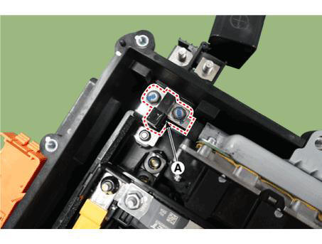
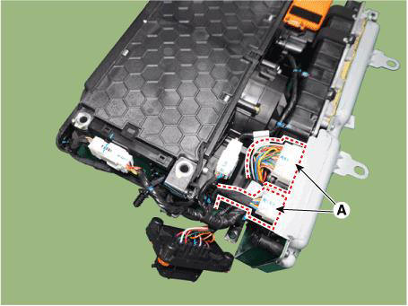
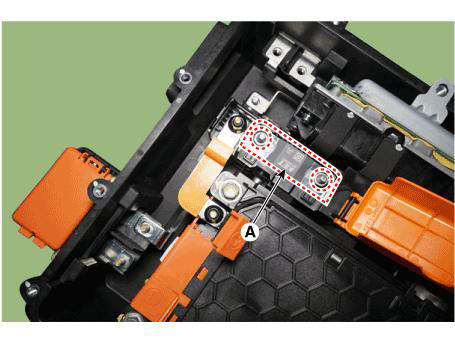
- Remove the BMS wiring harness terminal after loosening the mounting bolts (A).
Tightening torque : 7.8 - 11.8 N.m (0.8 - 1.2 kgf.m, 5.8 - 8.7 lb-ft)
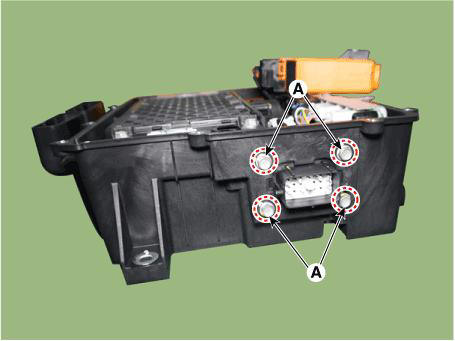
- Remove the 48V battery case assembly after loosening the mounting bolts (A).
Tightening torque : 7.8 - 11.8 N.m (0.8 - 1.2 kgf.m, 5.8 - 8.7 lb-ft)
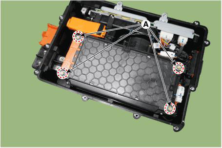
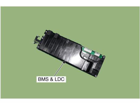
- Disconnect the BMS & LDC connectors (A).
- Remove the BMS & LDC assembly.
Installation
- Install in the reverse order of removal.
Description
Mounted in the power relay assembly (RPA), the main fuse protects the high voltage battery and high voltage circuits from overcurrent.
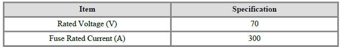
Specifications
Removal
- Turn the ignition switch OFF and disconnect the battery (-) terminal.
- Remove the battery cover (A) after loosening the mounting bolts.
Tightening torque : 7.8 - 11.8 N.m (0.8 - 1.2 kgf.m, 5.8 - 8.7 lb-ft)
- Remove the mounting nuts and remove the main fuse (A).
Tightening torque : 7.5 - 10.5 N.m (0.76 - 1.07 kgf.m, 5.5 - 7.7 lb-ft)
Installation
- Install in the reverse order of removal.
Specifications

READ NEXT:
 Power Relay Assembly (PRA) - Removal
Removal
Remove the PRA assembly.
(Refer to 48V Battery System - "Power Relay Assembly (PRA)")
Remove the PRA cover.
Remove the mounting bolts and remove the power relay busbar (A).
Disconnect the main relay connector
Battery Pack Assembly Inlet Duct/ Battery Pack
Assembly Outlet Duct
Removal and
Installation
Battery Pack Assembly Inlet Duct
Turn the ignition switch OFF and disconnect the battery (-) terminal.
Remove the luggage board (A).
Separate the inlet cooling duct (A) in the direction of the arrow.
Tigh
Battery Module Inlet Duct
Turn ignition switch OFF and disconnect the battery (-) terminal.
Remove the 48V battery assembly
(Refer to 48V Battery System - "Repair procedures")
Remove the battery cover (A) after loosening the mounting bolts.
Tightening
SEE MORE:
Front seat cushion cover
Component Location
Front seat cushion cover
Replacement
WARNING
When removing with a flat-tip screwdriver or remover, wrap
protective tape around the tools to
prevent damage to components.
Put on gloves to prevent hand injuries
Compressor - Disassembly
Disassembly
Remove the front tire RH.
(Refer to Suspension System - "Wheel")
Loosen the drive belt.
(Refer to Engine Mechanical System - "Drive Belt")
Remove the clutch bolt (A) while holding the pulley with a clutch b
Information
- Home
- Hyundai Tucson - Fourth generation (NX4) - (2020-2023) - Owner's Manual
- Hyundai Tucson - Fourth generation (NX4) - (2020-2023) - Workshop Manual
