Hyundai Tucson: Power Relay Assembly (PRA) - Removal
Hyundai Tucson - Fourth generation (NX4) - (2020-2023) - Workshop Manual / Engine Electrical System / 48V Battery System / Power Relay Assembly (PRA) - Removal
Removal
- Remove the PRA assembly.
(Refer to 48V Battery System - "Power Relay Assembly (PRA)")
- Remove the PRA cover.
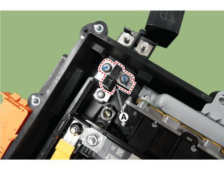
- Remove the mounting bolts and remove the power relay busbar (A).
- Disconnect the main relay connector (A).
- Remove the main relay (B).
Installation
- Install in the reverse order of removal.
Removal
- Turn ignition switch OFF and disconnect the battery (-) terminal.
- Remove the 48V battery assembly.
(Refer to 48V Battery System - "Repair procedures")
- Remove the battery cover (A) after loosening the mounting bolts.
Tightening torque : 7.8 - 11.8 N.m (0.8 - 1.2 kgf.m, 5.8 - 8.7 lb-ft)
- Remove the terminal capacitor (A) after loosening the mounting bolts.
Tightening torque : 7.8 - 11.8 N.m (0.8 - 1.2 kgf.m, 5.8 - 8.7 lb-ft)
- Remove the mounting uuts and remove the battery module (-) busbar (A).
Tightening torque : 7.8 - 11.8 N.m (0.8 - 1.2 kgf.m, 5.8 - 8.7 lb-ft)
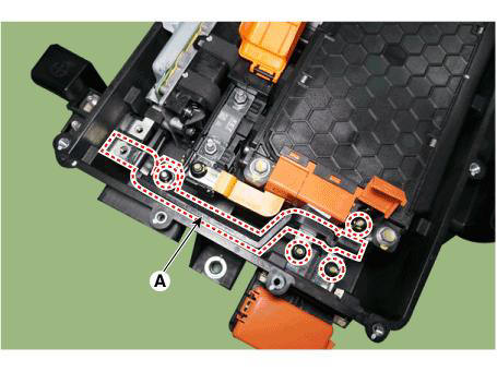
- Remove the mounting nuts and remove the battery module (+) busbar (A).
Tightening torque : 7.8 - 11.8 N.m (0.8 - 1.2 kgf.m, 5.8 - 8.7 lb-ft)

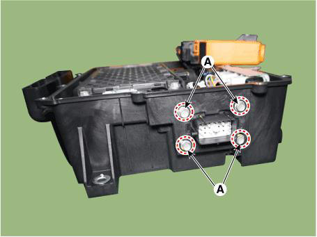
- Remove the BMS wiring harness terminal after loosening the mounting bolts (A).
Tightening torque : 7.8 - 11.8 N.m (0.8 - 1.2 kgf.m, 5.8 - 8.7 lb-ft)
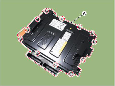
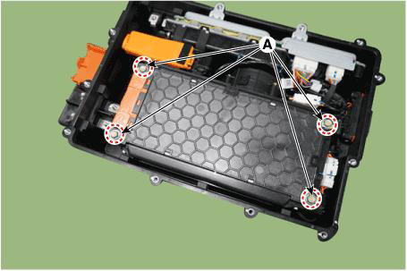
- Remove the 48V battery case assembly after loosening the mounting bolts (A).
Tightening torque : 7.8 - 11.8 N.m (0.8 - 1.2 kgf.m, 5.8 - 8.7 lb-ft)
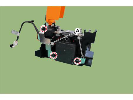
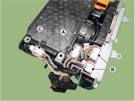
- Disconnect the PRA extension connector (A) and the BMS & LDC connectors (B).
- Disconnect the battery temperature sensor extension connector (C).
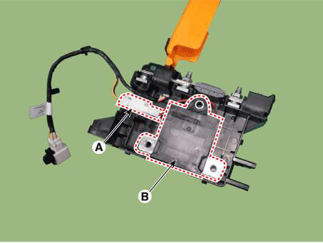
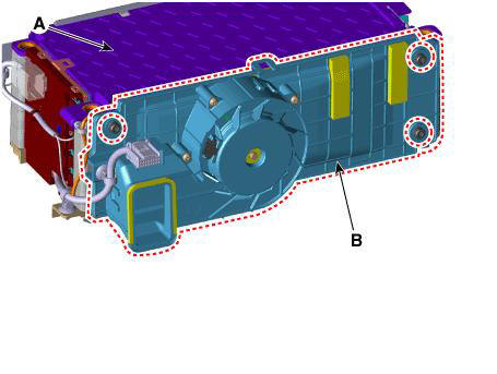
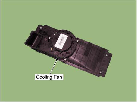
- Disconnect the cooling blower fan connector (A).
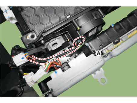
- Remove the battery cooling blower unit (B) from the battery module (A).
Tightening torque : 5.9 - 9.8 N.m (0.6 - 1.0 kgf.m, 4.3 - 7.2 lb-ft)
Installation
- Install in the reverse order of removal.
READ NEXT:
 Battery Pack Assembly Inlet Duct/ Battery Pack
Assembly Outlet Duct
Battery Pack Assembly Inlet Duct/ Battery Pack
Assembly Outlet Duct
Removal and
Installation
Battery Pack Assembly Inlet Duct
Turn the ignition switch OFF and disconnect the battery (-) terminal.
Remove the luggage board (A).
Separate the inlet cooling duct (A) in the direction of the arrow.
Tigh
Battery Module Inlet Duct
Turn ignition switch OFF and disconnect the battery (-) terminal.
Remove the 48V battery assembly
(Refer to 48V Battery System - "Repair procedures")
Remove the battery cover (A) after loosening the mounting bolts.
Tightening
Battery Module Inlet B Duct
Remove the 48V battery assembly.
(Refer to 48V Battery System - "Repair procedures")
Remove the battery pack assembly inlet duct B (A) after loosening the
mounting bolts.
Install in the reverse order of removal.
Sp
SEE MORE:
IMT System Learning Procedures - Adjustment
IMT System Learning Procedures Table
* Refer to the following table to perform the diagnostic tool learning
procedure.
IMT system learning stams can be checked through the cluster lamp.
Ill case by recompiled procedures (1)
Clear
Blower - Inspection
Connect the battery voltage and check the blower motor rotation.
If the blower motor does not operate well, substitute with a known-good
blower motor and check
for proper operation.
Replace the blower motor if it is proved that th
Information
- Home
- Hyundai Tucson - Fourth generation (NX4) - (2020-2023) - Owner's Manual
- Hyundai Tucson - Fourth generation (NX4) - (2020-2023) - Workshop Manual
