Hyundai Tucson: Battery Module Inlet B Duct
Hyundai Tucson - Fourth generation (NX4) - (2020-2023) - Workshop Manual / Engine Electrical System / 48V Battery System / Battery Module Inlet B Duct
- Remove the 48V battery assembly.
(Refer to 48V Battery System - "Repair procedures")
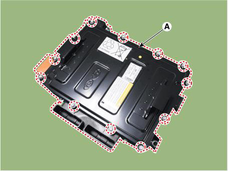
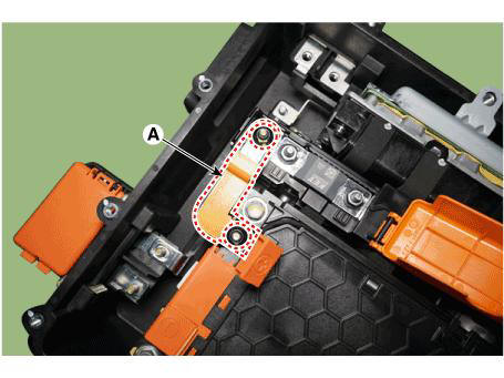
- Remove the battery pack assembly inlet duct B (A) after loosening the mounting bolts.

- Install in the reverse order of removal.
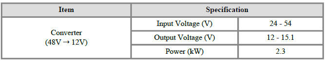
Specifications
Removal
- Turn ignition switch OFF and disconnect the battery (-) terminal.
- Remove the 48V battery assembly.
(Refer to 48V Battery System - "Repair procedures")
- Remove the battery cover (A) after loosening the mounting bolts.
Tightening torque : 7.8 - 11.8 N.m (0.8 - 1.2 kgf.m, 5.8 - 8.7 lb-ft)
- Remove the terminal capacitor (A) after loosening the mounting bolts.
Tightening torque : 7.8 - 11.8 N.m (0.8 - 1.2 kgf.m, 5.8 - 8.7 lb-ft)
- Remove the mounting nuts and remove the battery module (-) busbar (A).
Tightening torque : 7.8 - 11.8 N.m (0.8 - 1.2 kgf.m, 5.8 - 8.7 lb-ft)
- Remove the mounting nuts and remove the battery module (+) busbar (A).
Tightening torque : 7.8 - 11.8 N.m (0.8 - 1.2 kgf.m, 5.8 - 8.7 lb-ft)
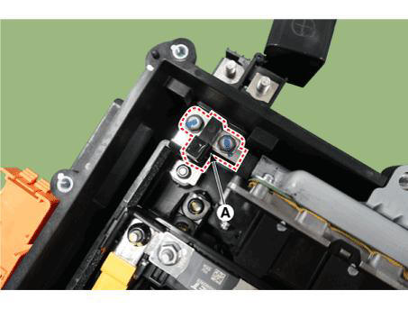
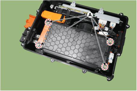
- Remove the BMS wiring harness terminal after loosening the mounting bolts (A).
Tightening torque : 7.8 - 11.8 N.m (0.8 - 1.2 kgf.m, 5.8 - 8.7 lb-ft)
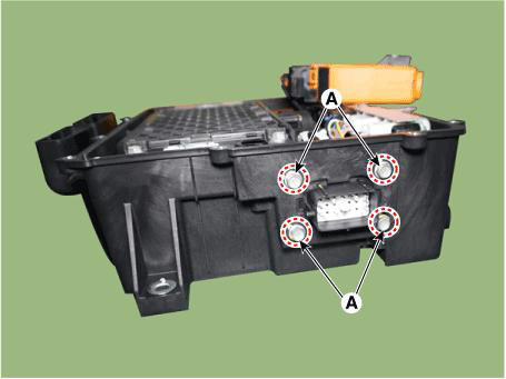
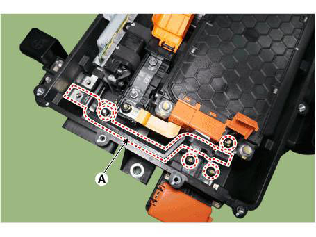
- Remove the 48V battery case assembly after loosening the mounting bolts (A).
Tightening torque : 7.8 - 11.8 N.m (0.8 - 1.2 kgf.m, 5.8 - 8.7 lb-ft)
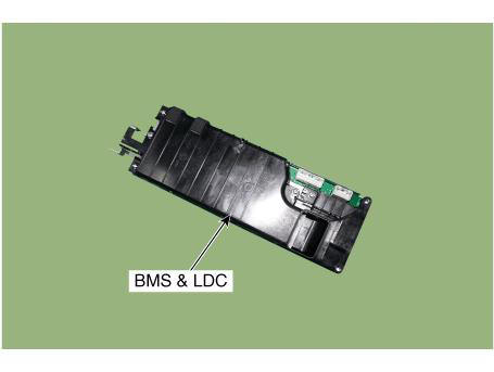
- Disconnect the BMS & LDC connectors (A).
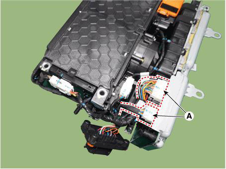
- Remove the BMS & LDC assembly.
Installation
- Install in the reverse order of removal.
READ NEXT:
 Engine Room Under Cover
Removal
Turn the ignition switch OFF and disconnect the battery (-) terminal.
Remove the engine room under cover.
(Refer to Engine Mechanical System - "Engine Room Under Cover")
Disconnect the ground cable (A).
Tightening to
Engine Mechanical System
Components
Pulley
Stator assembly
Rotor assembly
Brush holder assembly
Front bracket assembly
Rear bracket assembly
Inverter assembly
Removal
Turn the ignition switch OFF and disconnect the battery (-) terminal.
Disconnec
SEE MORE:
Front Door - Replacement
Remove the outside rear view mirror.
(Refer to Mirror - "Outside Rear View Mirror")
Remove the front door belt outside weatherstrip (A).
To install, reverse the removal procedure.
WARNING
Replace any damaged clips (or p
Front door window glass
Component Location
Front door window glass
Replacement
Remove the front door trim.
(Refer to Front Door - "Front Door Trim")
Remove the front door belt inside weatherstrip.
(Refer to Front Door - "Front Door Belt I
Information
- Home
- Hyundai Tucson - Fourth generation (NX4) - (2020-2023) - Owner's Manual
- Hyundai Tucson - Fourth generation (NX4) - (2020-2023) - Workshop Manual
