Hyundai Tucson: Engine Room Under Cover
Hyundai Tucson - Fourth generation (NX4) - (2020-2023) - Workshop Manual / Engine Electrical System / 48V Battery System / Engine Room Under Cover
Removal
- Turn the ignition switch OFF and disconnect the battery (-) terminal.
- Remove the engine room under cover.
(Refer to Engine Mechanical System - "Engine Room Under Cover")
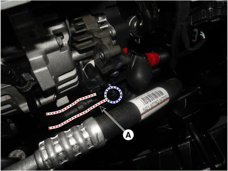
- Disconnect the ground cable (A).
Tightening torque : 18.6 - 24.5 N.m (1.9 - 2.5 kgf.m, 13.7 - 18.1 lb-ft)
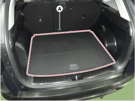
- Remove the luggage board (A).
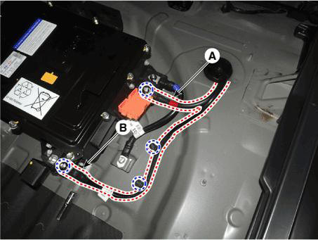
- Disconnect the inverter power cable (A) and 12V (+) cable (B).
Tightening torque : 26.5 - 32.4 N.m (2.7 - 3.3 kgf.m, 19.5 - 23.9 lb-ft)
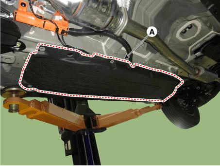
- Remove the RH floor under cover (A).
Tightening torque : 9.8 - 11.8 N.m (1.0 - 1.2 kgf.m, 7.2 - 8.7 lb-ft)
- Disconnect the extension connector (A).
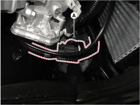
- Remove the rear cross member.
(Refer to Suspension System - "Rear Cross Member")
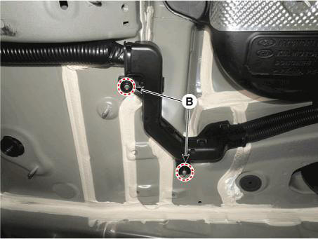
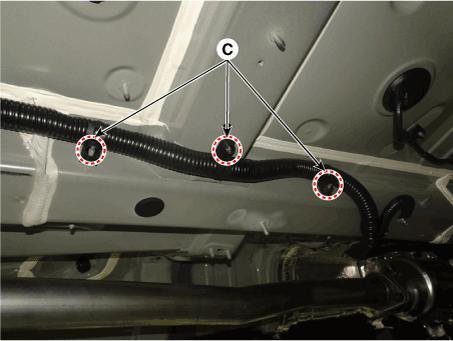
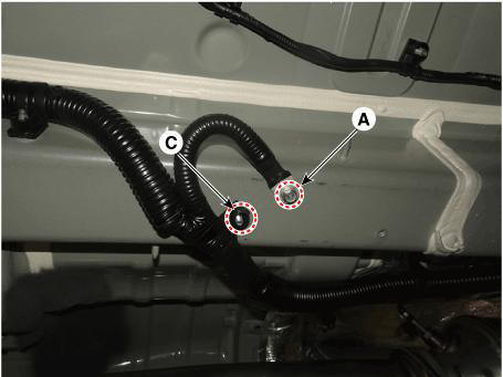
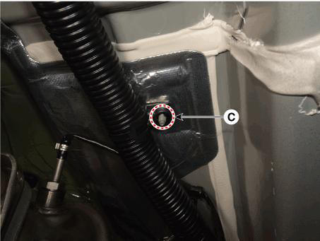
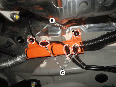
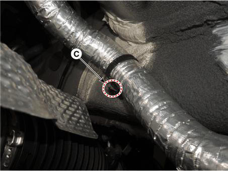
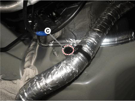
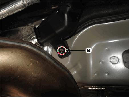
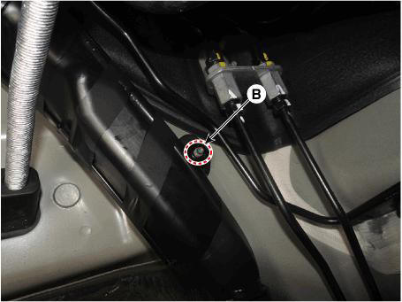
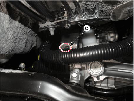
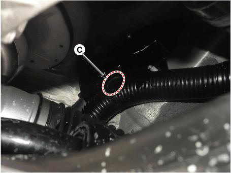
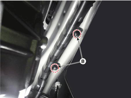
- Remove the 48V battery power cable ground bolt (A), nuts (B) and then separate the fastener (C) and bracket (D).
Tightening torque :
Bolt : 9.8 - 11.8 N.m (1.0 - 1.2 kgf.m, 7.2 - 8.7 lb-ft)
Nuts : 7.8 - 9.8 N.m (0.8 - 1.0 kgf.m, 5.8 - 7.2 lb-ft)
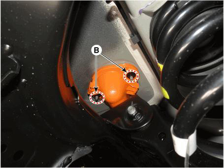
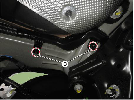
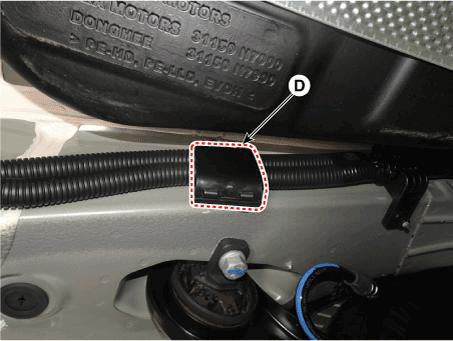
- Remove the 48V battery power cable.
Installation
- Install in the reverse order of removal.
READ NEXT:
 Engine Mechanical System
Components
Pulley
Stator assembly
Rotor assembly
Brush holder assembly
Front bracket assembly
Rear bracket assembly
Inverter assembly
Removal
Turn the ignition switch OFF and disconnect the battery (-) terminal.
Disconnec
Vehicle parasitic current inspection
Inspection
Using the Ammeter
Turn the all electric devices OFF, and then turn the ignition switch OFF.
Close all doors except the engine hood, and then lock all doors.
(1) Disconnect the hood switch connector.
(2) Close the trunk lid.
SEE MORE:
Exterior features
Roof rack
Your vehicle may come equipped with
roof rack rails. If your vehicle is equipped
with roof rack rails, you may be able to
add roof rack crossbars as an accessory
(not shown).
NOTICE
If the vehicle is equipped with a
sunroof, be su
Tail Gate - Replacement
Replacement
Tailgate upper trim
WARNING
When removing with a flat-tip screwdriver or remover, wrap
protective tape around the tools to
prevent damage to components.
Put on gloves to prevent hand injuries.
Using a screwdriver or rem
Information
- Home
- Hyundai Tucson - Fourth generation (NX4) - (2020-2023) - Owner's Manual
- Hyundai Tucson - Fourth generation (NX4) - (2020-2023) - Workshop Manual
