Hyundai Tucson: 48V Battery System - Repair procedures (Removal)
- Turn ignition switch OFF and disconnect the battery (-) terminal.
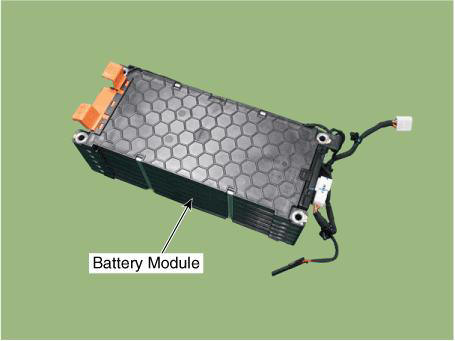
- Remove the 48V battery assembly.
(Refer to 48V Battery System - "Repair procedures")
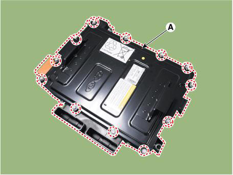
- Remove the battery cover (A) after loosening the mounting bolts.
Tightening torque : 7.8 - 11.8 N.m (0.8 - 1.2 kgf.m, 5.8 - 8.7 lb-ft)
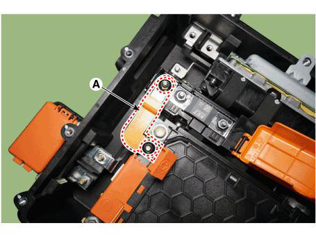
- Remove the terminal capacitor (A) after loosening the mounting bolts.
Tightening torque : 7.8 - 11.8 N.m (0.8 - 1.2 kgf.m, 5.8 - 8.7 lb-ft)
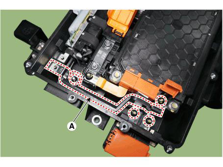
- Remove the mounting nuts and remove the battery module (-) busbar (A).
Tightening torque : 7.8 - 11.8 N.m (0.8 - 1.2 kgf.m, 5.8 - 8.7 lb-ft)

- Remove the mounting nuts and remove the battery module (+) busbar (A).
Tightening torque : 7.8 - 11.8 N.m (0.8 - 1.2 kgf.m, 5.8 - 8.7 lb-ft)

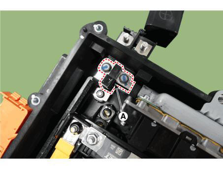
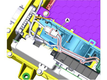
- Remove the BMS wiring harness terminal after loosening the mounting bolts (A).
Tightening torque : 7.8 - 11.8 N.m (0.8 - 1.2 kgf.m, 5.8 - 8.7 lb-ft)
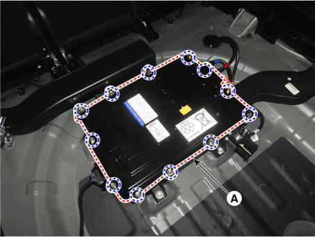
- Remove the 48V battery case assembly after loosening the mounting bolts (A).
Tightening torque : 7.8 - 11.8 N.m (0.8 - 1.2 kgf.m, 5.8 - 8.7 lb-ft)
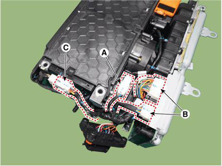
- Disconnect the PRA extension connector (A) and the BMS & LDC connectors (B).
- Disconnect the battery temperature sensor extension connector (C).
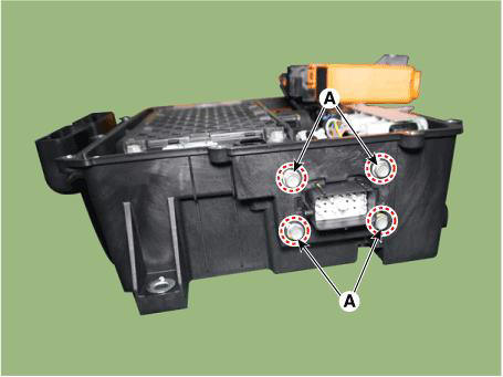
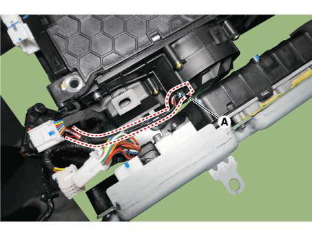
- Disconnect the cooling blower fan connector (A).
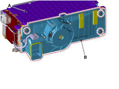
- Remove the battery cooling blower unit (B) from the battery module (A).
Tightening torque : 5.9 - 9.8 N.m (0.6 - 1.0 kgf.m, 4.3 - 7.2 lb-ft)
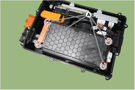
- Remove the battety module lnlet duct (A) after loosening mountin bolts.
Tightening torque : 3.4 - 6.4 N.m (0.35 - 0.65 kgf.m, 2.5 - 4.7 lb-ft)
Installation
- Install in the reverse order of removal.
Description
The Power Relay Assembly (PRA) consists of the positive main relay. It is located inside the battery pack assembly and controls the high voltage power circuit between the high voltage battery and inverter by the control signal of BMS ECU.
Removal
- Turn ignition switch OFF and disconnect the battery (-) terminal.
- Remove the battery cover (A) after loosening the mounting bolts.
Tightening torque : 7.8 - 11.8 N.m (0.8 - 1.2 kgf.m, 5.8 - 8.7 lb-ft)
- Disconnect the PRA extension connector (A).
- Remove the terminal capacitor (A) after loosening the mounting bolts.
Tightening torque : 7.8 - 11.8 N.m (0.8 - 1.2 kgf.m, 5.8 - 8.7 lb-ft)

- Remove the mounting nuts and remove the battery module (-) busbar (A).
Tightening torque : 7.8 - 11.8 N.m (0.8 - 1.2 kgf.m, 5.8 - 8.7 lb-ft)
- Remove the mounting nuts and remove the battery module (+) busbar (A).
Tightening torque : 7.8 - 11.8 N.m (0.8 - 1.2 kgf.m, 5.8 - 8.7 lb-ft)
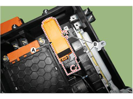
- Remove the PRA assembly (A) after loosening the mounting bolts (B).
Tightening torque : 7.8 - 11.8 N.m (0.8 - 1.2 kgf.m, 5.8 - 8.7 lb-ft)
Installation
- Install in the reverse order of removal.
READ NEXT:
 BMS ECU Terminal and Input/Output Signal
Terminal Function
Connector B10-A
Connector B01-B
Removal
Turn ignition switch OFF and disconnect the battery (-) terminal.
Remove the 48V battery assembly.
(Refer to 48V Battery System - "Repair procedures")
Power Relay Assembly (PRA) - Removal
Removal
Remove the PRA assembly.
(Refer to 48V Battery System - "Power Relay Assembly (PRA)")
Remove the PRA cover.
Remove the mounting bolts and remove the power relay busbar (A).
Disconnect the main relay connector
Battery Pack Assembly Inlet Duct/ Battery Pack
Assembly Outlet Duct
Removal and
Installation
Battery Pack Assembly Inlet Duct
Turn the ignition switch OFF and disconnect the battery (-) terminal.
Remove the luggage board (A).
Separate the inlet cooling duct (A) in the direction of the arrow.
Tigh
SEE MORE:
Start/Stop Button (SSB)
A single stage push button is used for the driver to operate the vehicle.
Pressing this button allows:
To activate the power modes ' O f f . 'Accessory', 'Ignition' and
'Start' by switching the corresponding t
DCT (Dual Clutch Transmission) System (SBW)- Installation
Installation
To install, reverse the removal procedure.
WARNING
Matters that require attention when installing the dual clutch
transmission (DCT) to engine
l)Check the pilot bearing (B) and external damper (A) 011 the side of engine for
Information
- Home
- Hyundai Tucson - Fourth generation (NX4) - (2020-2023) - Owner's Manual
- Hyundai Tucson - Fourth generation (NX4) - (2020-2023) - Workshop Manual
