Hyundai Tucson: Suction & Liquid Pipe Assembly
Components
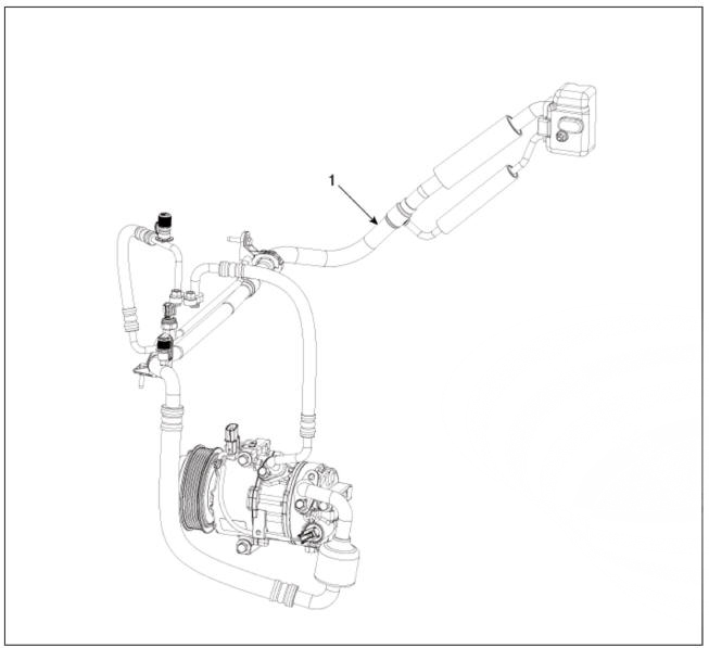
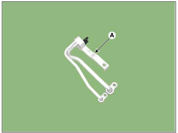
- Suction & Liquid Pipe Assembly
Replacement
- If a compressor is available, the air conditioner is operated for a few minutes in the engine idle state and then the engine is stopped.
- Disconnect the negative (-) batteiy terminal.
- Recover the refrigerant with a recovery/charging station.
(Refer to Air conditioning System - "Repair procedures")
- Remove the engine cover.
(Refer to Engine Mechanical System - "Engine Cover")
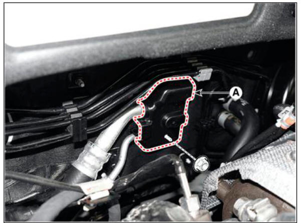
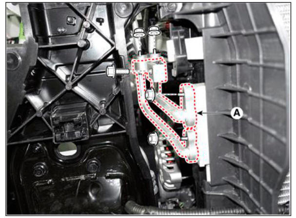
- Loosen the mounting nut and separate the expansion valve cover (A).
Tightening torque : 7.8 - 11.8 N.m (0.8 - 1.2 kgf.m, 5.8 - 8.7 lb-ft)
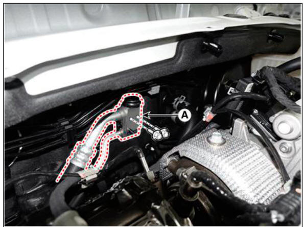
- Loosen the mounting bolts and separate the expansion valve (A) fron evaporator core.
Tightening torque : 21.6 - 32.4 N.m (2.2 - 3.3 kgf.m, 15.9 - 23.9 lb-ft)
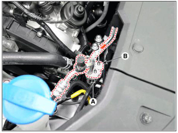
- Loosen the mounting nuts and separate the suction line (A), discharge line (B).
Tightening torque : 19.6 - 23.5 N.m (2.0 - 2.4 kgf.m. 14.5 - 17.4 lb-ft)
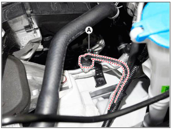
- Disconnect the APT sensor connector (A).
- Remove the engine room under cover.
(Refer to Engine Mechanical System - "Engine Room Under Cover")
- Remove the engine mounting braket.
(Refer to Engine Mechanical System - "Engine Mounting")
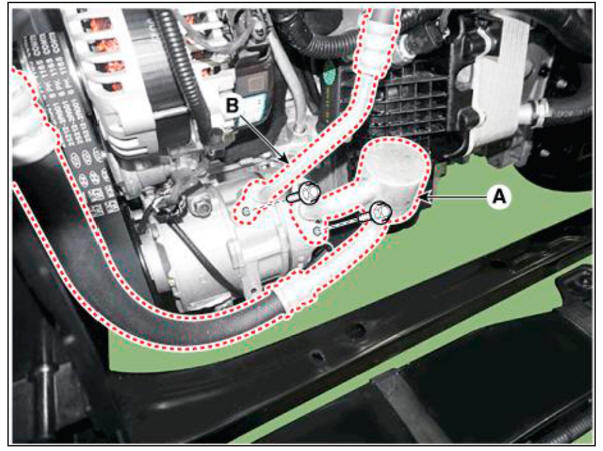
- Separate the compressor suction line (A) and discharge line (B) connection nuts and disconnect the line.
Tightening torque : 21.6 - 32.4 N.m (2.2 - 3.3 kgf.m, 15.9 - 23.9 lb-ft)
WARNING
Be care fill not to damage the parts located under the vehicle (floor under cover, fuel filter, fuel tank and canister) when raising the vehicle using the lift.
(Refer to General Information - "Lift and Support Points")
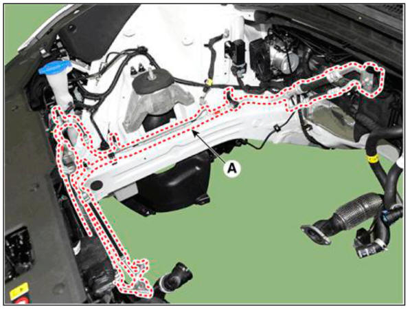
- Loosen the mounting bolt and remove the Front suction & Liquid pipe assembly (A).
Tightening torque : 7.8 - 11.8 N.m (0.8 - 1.2 kgf.m, 5.8 - 8.7 lb-ft)
- Install in the reverse order of removal.
WARNING
- Plug or cap the lines immediately after disconnecting them to avoid moisture and dust contamination.
- Tighten the bolt or nut joint to the specified torque.
- Using a gas leak detector, check for refrigerant leakage.
- Evacuate air in the refrigeration system and charge system with refrigerant.
Capacity :
R-1234yf: 550 +- 25g (17.7 = 0.88oz)
R-134a : 600 +- 25g (19.29 +- 0.88oz)
Refrigerant Line (Condenser)
- Remove the front bumper assembly.
(Refer to Body (Interior and Exterior) - "Front Bumper Assembly")
- Recover the refrigerant with a recovery/charging station.
(Refer to Air conditioning System - "Repair procedures")
- Loosen the mounting nuts, and then disconnect the liquid line (A) from the condenser.
Tightening torque : 7.8 - 11.8 N.m (0.8 - 1.2 kgf.m, 5.8 - 8.7 lb-ft)
- Install in the reverse order of removal.
WARNING
- Plug or cap the lines immediately after disconnecting them to avoid moisture and dust contamination.
- Tighten the bolt or nut joint to the specified torque.
- Using a ga s leak detector," check for refrige rant leakage.
- Evacuate air in the refrigeration system and charge system with refrigerant.
Capacity : R-1234yf: 550 +- 25g (17.7 +- 0.88oz)
R-134a : 600 +- 25g (19.29 +- 0.88oz)
Description
The compressor is the power unit of the A/C system.
It is located on the side of engine block and driven by a V-belt of the engine.
The compressor changes low pressure and low temperature refrigerant gas into high pressure and high temperature refrigerant
Variable Swash Plate Compressor
The compressor has a swash plate that rotates to reciprocate pistons, which compress refrigerant.
The variable swash plate compressor controls the swash plate angle to change the refrigerant displacement. It achieves precise cooling capability control in accordance with vehicle interior and driving conditions.
The internally controlled variable swash plate compressor changes the swash plate angle by a MCV (Mechanical Control Valve) in accordance with fluctuation of a suction pressure.
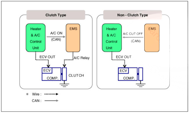
The externally controlled variable swash plate compressor changes the swash plate angle by an ECV (Electric Control Valve) in accordance with an electrical signal from the heater & A/C control unit. This enables stable temperature control and improved driving sensation.
ECV Control Diagram
READ NEXT:
 Compressor
Components
Compressor
Components
Clutch bolt
Disc & Hub assembly
Snap ring (Rotor)
Pulley
Snap Ring (Stator)
Clutch spacer
Compressor
Electric Control Valve (ECV)
Electric Control Valve (ECV) snap ring
Removal
Compressor - Installation
Make sure that the compressor (A) mounting bolt of the correct length is
screwed in. Tighten the mounting bolts in the
specified tightening order.
Install in the reverse order of removal.
f you install a new compressor, drain
External Control Valve Compressor Inspection (GDS)
Compressor type: Fixed type compressor, External control valve, Internal
control valve.
In cases of fixed type and internal control valve, it is possible to inspect
compressor's operation with clutch noise.
When it comes to External con
SEE MORE:
Smart Cruise Control (SCC)
Smart Cruise Control is designed to
help detect the vehicle ahead and
help maintain the desired speed and
minimum distance between the vehicle
ahead.
Overtaking Acceleration Assist
While Smart Cruise Control is operating,
if the function judge
Ignition Switch Assembly
Removal
Disconnect the negative (-) batteiy terminal.
Remove the steering column upper and lower shrouds.
(Refer to Body - "Steering Column Shroud Panel")
Remove the ignition switch (A) after disconnecting the 6P connector (B).
Information
- Home
- Hyundai Tucson - Fourth generation (NX4) - (2020-2023) - Owner's Manual
- Hyundai Tucson - Fourth generation (NX4) - (2020-2023) - Workshop Manual
