Hyundai Tucson: Rear Suspension System - Removal
WARNING
When lifting a vehicle using a lift, be careful not to damage the lower parts of the vehicle (floor under cover, fuel filter, fuel tank, canister).
(Refer to General Information - "Lift Point")
- Loosen the rear wheel nuts slightly.
Raise the vehicle, and make sure it is securely supported.
- Remove the rear wheel and tire.
(Refer to Suspension System - "Wheel")
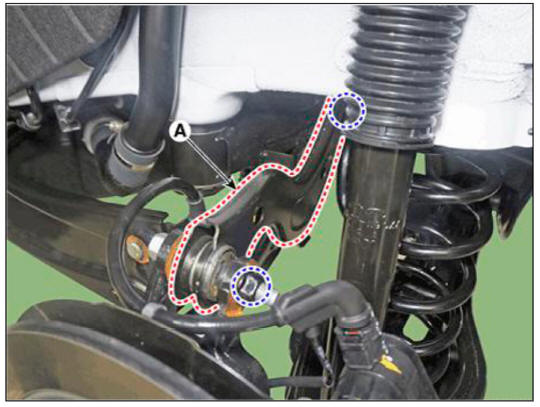
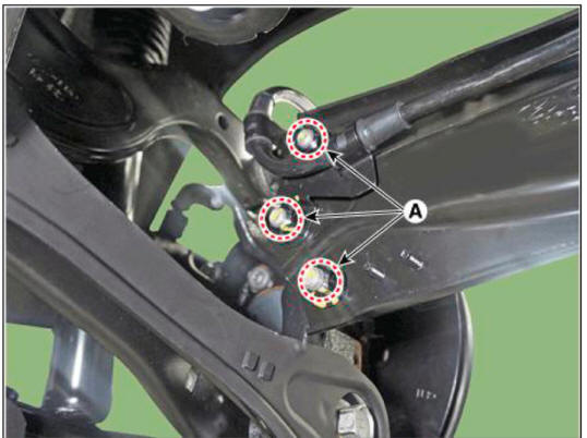
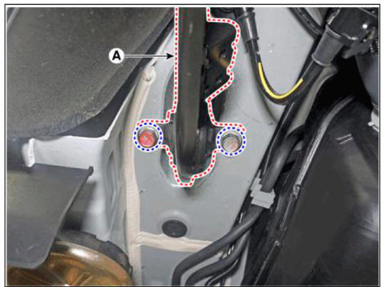
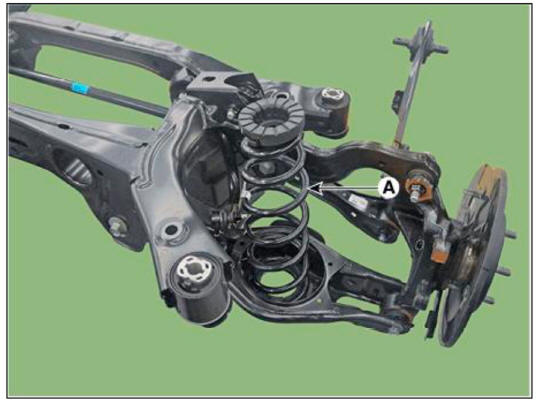
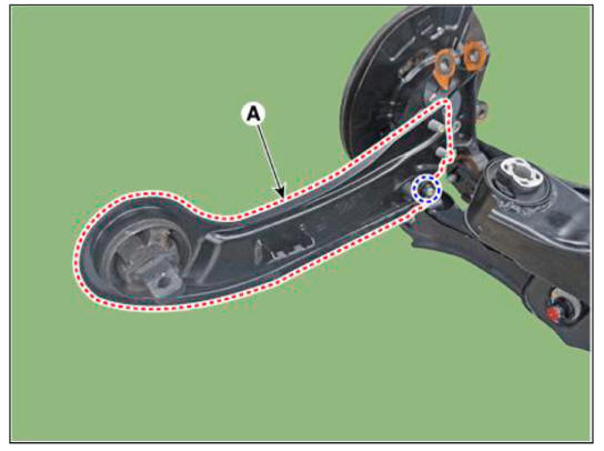
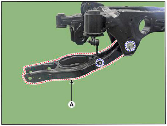
- Remove the rear upper arm (A) after loosening the mounting bolts and nuts.
Tightening torque : 137.2 - 156.9 N.m (14.0- 16.0kgf.m, 101.2- 115.7 lb-ft)
WARNING
Set up the transmission jack under the lower arm in order to remove it in no-load condition.
Inspection
- Check the bushing for wear and deterioration.
- Check the rear upper arm or damage and deformation.
- Check for all bolts and nut.
Installation
- To install, reverse the removal procedures.
- Check the alignment.
(Refer to Suspension System - "Alingment")
Removal
WARNING
When lifting a vehicle using a lift, be careful not to damage the lower parts of the vehicle (floor under cover, fuel filter, fuel tank, canister).
(Refer to General Information - "Lift Point")
- Loosen the rear wheel nuts slightly.
Raise the vehicle, and make sure it is securely supported.
- Remove the rear wheel and tire.
(Refer to Suspension System - "Wheel")
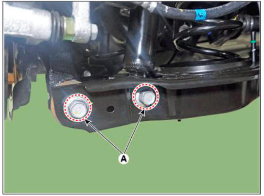
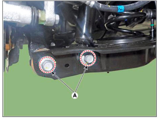
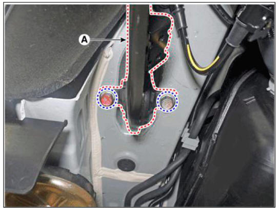
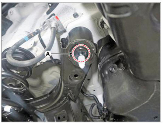
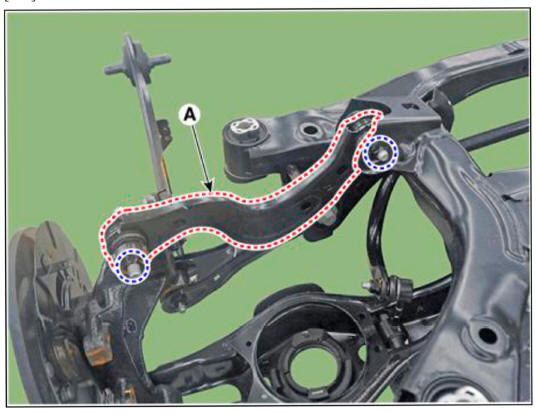
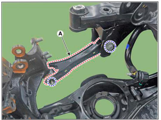
- Remove the rear lower arm from the rear axle after loosening the mounting bolts and nuts (A).
Tightening torque : 137.2 - 156.9 N.m (14.0- 16.0kgf.m, 101.2- 115.7 lb-ft)
WARNING
SSet up the transmission jack under the lower arm in order to remove it in no-load condition.
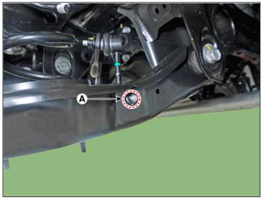
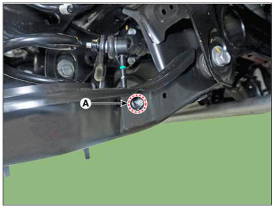
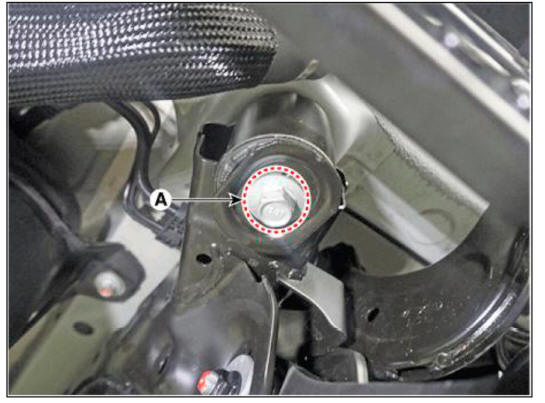
- Remove the stabilizer bar link from the rear lower arm after loosening the mounting nut (A).
Tightening torque : 49.0 - 58.8 N.m (5.0 - 6.0 kgf.m, 36.2 - 43.4 lb-ft)
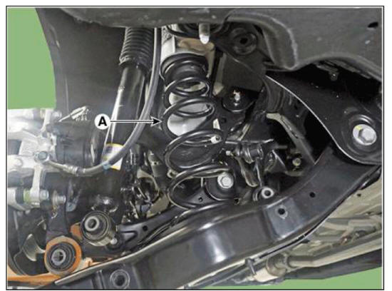
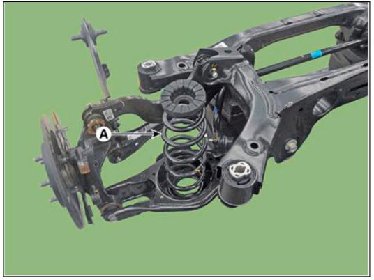
- Remove the coil spring (A).

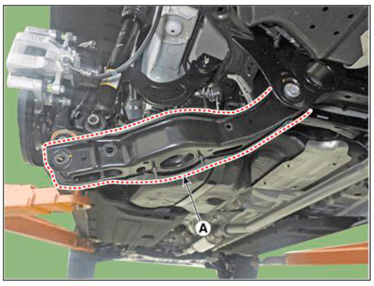
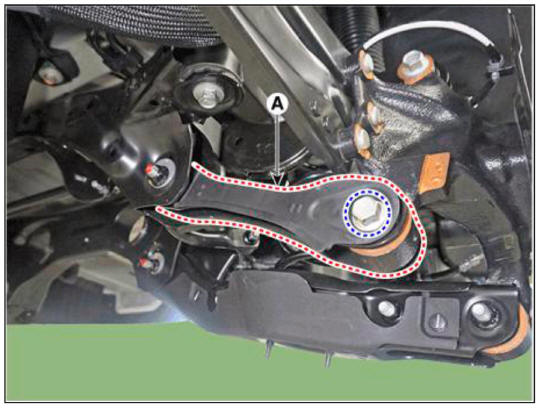
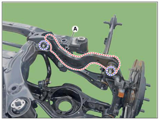
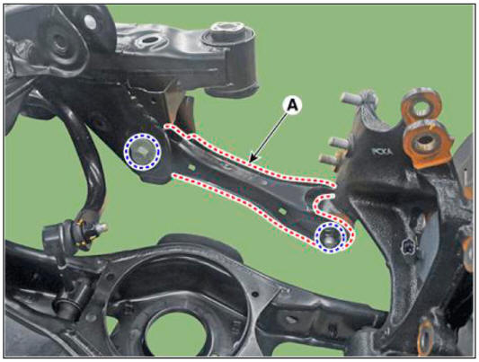
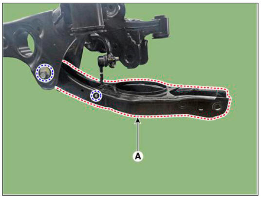
- Remove the rear lower arm (A) after loosening the mounting bolt and nut.
Tightening torque : 137.2 - 156.9 N.m (14.0- 16.0kgf.m, 101.2- 115.7 lb-ft)
Inspection
- Check the bushing for wear and deterioration.
- Check the rear lower arm for deformation.
- Check the coil spring and spring pad for deterioration and deformation.
- Check for all bolts and nut.
Installation
- To install, reverse the removal procedures.
- Check the alignment.
(Refer to Suspension System - "Alingment")
Removal
WARNING
When lifting a vehicle using a lift, be careful not to damage the lower parts of the vehicle (floor under cover, fuel filter, fuel tank, canister).
(Refer to General Information - "Lift Point")
- Loosen the rear wheel nuts slightly.
Raise the vehicle, and make sure it is securely supported.
- Remove the rear wheel and tire.
(Refer to Suspension System - "Wheel")
- Remove the rear lower arm from the rear axle after loosening the mounting bolts and nuts (A).
Tightening torque : 137.2 - 156.9 N.m (14.0- 16.0kgf.m, 101.2- 115.7 lb-ft)
WARNING
Set up the transmission jack under the lower arm in order to remove it in no-load condition.
- Remove the stabilizer bar link from the rear lower arm after loosening the mounting nut (A).
Tightening torque : 49.0 - 58.8 N.m (5.0 - 6.0 kgf.m, 36.2 - 43.4 lb-ft)
- Remove the coil spring (A).
Inspection
- Check the spring for distortion, aging or damage.
- Check the spring upper pad and lower pad for aging or damage.
Installation
- To install, reverse the removal procedures.
- Check the alignment.
(Refer to Suspension System - "Alingment")
Removal
WARNING
When lifting a vehicle using a lift, be careful not to damage the lower parts of the vehicle (floor under cover, fuel filter, fuel tank, canister).
(Refer to General Information - "Lift Point")
- Loosen the rear wheel nuts slightly.
Raise the vehicle, and make sure it is securely supported.
- Remove the rear wheel and tire.
(Refer to Suspension System - "Wheel")
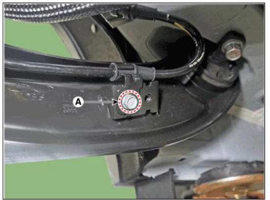
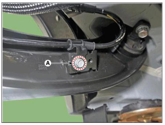
- Loosen the wheel speed sensor cable bracket mounting nuts (A).
Tightening torque : 12.7 - 16.7 N.m (1.3-1.7 kgf.m, 9.4 - 12.3 lb-ft)
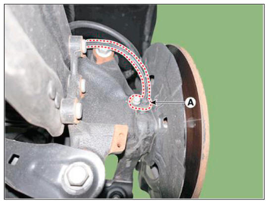
- Separate the trailing arm after loosening the mounting nuts (A).
Tightening torque : 98.0 - 117.6 N.m (10.0 - 12.0 kgf.m. 72.3 - 86.7 lb-ft)
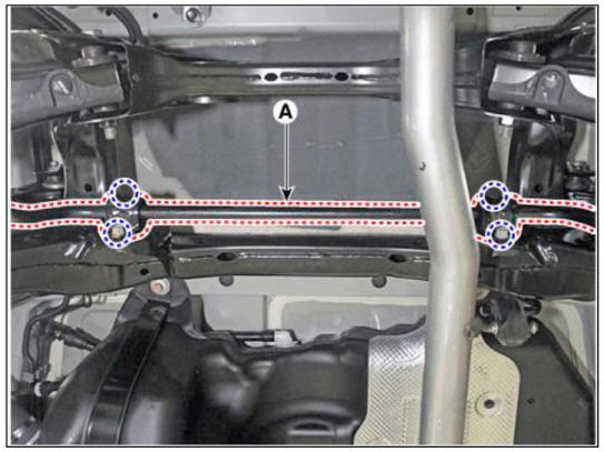
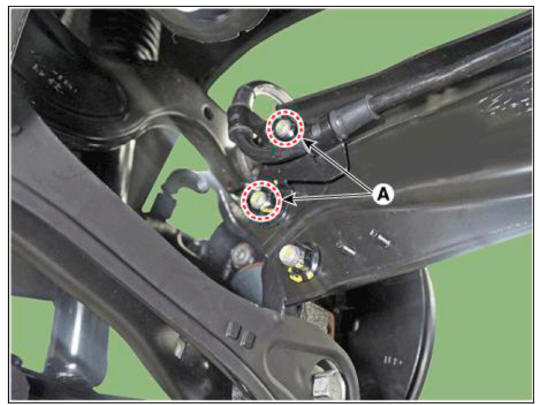
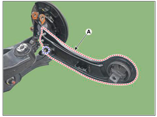
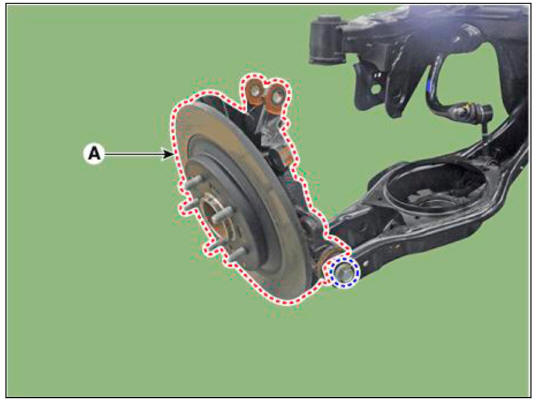
- Remove the trailing arm (A) after loosening the mounting bolts.
Tightening torque : 98.0 - 117.6 N.m (10.0 - 12.0 kgf.m, 72.3 - 86.7 lb-ft)
Inspection
- Check the bushing for wear and deterioration.
- Check for all bolts and nuts.
Installation
- To install, reverse the removal procedures.
- Check the alignment.
(Refer to Suspension System - "Alingment")
Removal
WARNING
When lifting a vehicle using a lift, be careful not to damage the lower parts of the vehicle (floor under cover, fuel filter, fuel tank, canister).
(Refer to General Information - "Lift Point")
- Loosen the rear wheel nuts slightly.
Raise the vehicle, and make sure it is securely supported.
- Remove the rear wheel and tire.
(Refer to Suspension System - "Wheel")
- Remove the rear assist arm (A) after loosening the mounting bolts and nuts.
Tightening torque :
Rear sub frame side : 137.3 - 156.9 N.m (14.0 - 16.0 kgf.m. 101.3 - 115.7 lb-ft)
Rear carrier side : 156.9 - 176.5 N.m (16.0 - 18.0 kgf.m, 115.7 - 130.2 lb-ft)
WARNING
Set up the transmission jack under the lower arm in order to remove it in no-load condition.
Inspection
- Check the bushing for wear and deterioration.
- Check for all bolts and nuts.
Installation
- To install, reverse the removal procedures.
- Check the alignment.
(Refer to Suspension System - "Alingment")
Removal
WARNING
When lifting a vehicle using a lift, be careful not to damage the lower parts of the vehicle (floor under cover, fuel filter, fuel tank, canister).
(Refer to General Information - "Lift Point")
- Raise the vehicle, and make sure it is securely supported.
- In the case of 4WD vehicle, remove the rear differential assembly.
(Refer to Driveshaft and axle - "Rear Differential Carrier")
- Remove the rear stabilizer link after loosening the mounting nut (A).
Tightening torque : 49.0 - 58.8 N.m (5.0 - 6.0 kgf.m, 36.2 - 43.4 lb-ft)

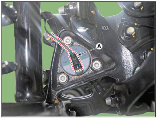
- Remove the rear wheel speed sensor (A) after loosening the mounting bolt.
Tightening torque : 53.9 - 63.7 N.m (5.5 - 6.5 kgf.m, 39.8 - 47.0 lb-ft)
Inspection
- Check the rear stabilizer bar for deformation.
- Check the rear stabilizer link ball joint for damage.
Installation
- To install, reverse the removal procedures.
- Check the alignment.
(Refer to Suspension System - "Alingment")
Removal
WARNING
When lifting a vehicle using a lift, be careful not to damage the lower parts of the vehicle (floor under cover, fuel filter, fuel tank, canister).
(Refer to General Information - "Lift Point")
- Loosen the rear wheel nuts slightly.
Raise the vehicle, and make sure it is securely supported.
- Remove the rear wheel and tire.
(Refer to Suspension System - "Wheel")
- Remove the rear brake caliper.
(Refer to Brake System - "Rear Disc Brake")
- In the case of 4WD vehicle, remove the rear differential assembly.
(Refer to Driveshaft and axle - "Rear Differential Carrier")
- Remove the center muffler.
(Refer to Engine Mechanical System - "Muffler")
- Disconnect the rear wheel speed sensor connector (A).
2WD
- Remove the rear wheel speed sensor (A) after loosening the mounting bolt.
Tightening torque : 8.8 - 13.7 N.m (0.9 - 1.4 kgf.m, 6.5 - 10.1 lb-ft)
4WD
- Loosen the wheel speed sensor cable bracket mounting nuts (A).
Tightening torque: 981) - 117^6 N.m (10.0 - 12.0 kgf.m, 72.3 - 86.7 lb-ft)
- Loosen the wheel speed sensor cable bracket mounting bolt (A).
Tightening torque : 12.7 - 16.7 N.m (1.3 - 1.7 kgf.m, 9.4 - 12.3 lb-ft)
- 29. Separate the trailing arm (A) after loosening the mounting nuts (A
Tightening torque: 98.0 - 117.6 N.m (10.0 - 12.0 kgf.m, 72.3 - 86.7 lb-ft)
- Support the jack on the lower part of the sub frame.
- Loosen the sub frame mounting nut (A).
Tightening torque : 156.9 - 176.5 N.m (16.0- 18.0 kgf.m, 115.7- 130.2 lb-ft)
- Loosen the sub frame mounting bolt (A).
Tightening torque : 156.9 - 176.5 N.m (16.0- 18.0 kgf.m, 115.7- 130.2 lb-ft)
- Remove the rear sub frame.
- Remove the coil spring (A).
LH
RH
- Remove the rear assist arm (A) after loosening the mounting bolts and nuts.
Tightening torque : 137.2 - 156.9 N.m (14.0- 16.0 kgf.m. 101.2- 115.7 lb-ft)
LH
RH
- Remove the trailing arm (A) after loosening the mounting nuts.
Tightening torque : 98.0 - 117.6 N.m (10.0 - 12.0 kgf.m. 72.3 - 86.7 lb-ft)
LH
RH
- Remove the rear assist arm (A) after loosening the mounting bolts and nuts.
Tightening torque :
Rear sub frame side : 137.3 - 156.9 N.m (14.0 - 16.0 kgf.m, 101.3 - 115.7 lb-ft)
Rear carrier side : 156.9 - 176.5 N.m (16.0 - 18.0 kgf.m. 115.7 - 130.2 lb-ft)
LH
RH
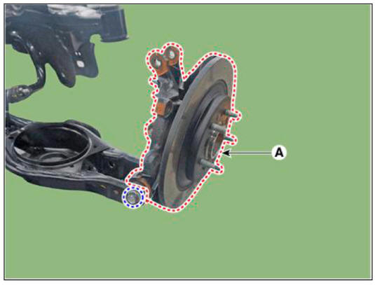
- Remove the rear carrier (A) from the rear lower arm after loosening the mounting bolt and nut.
Tightening torque : 137.2 - 156.9 N.m (14.0- 16.0 kgf.m. 101.2- 115.7 lb-ft)
LH
RH
- Remove the rear assist arm (A) after loosening the mounting bolts and nuts.
Tightening torque :
Rear stabilizer bar link side : 49.0 - 58.8 N.m (5.0 - 6.0 kgf.m. 36.2 - 43.4 lb-ft)
Rear sub frame side : 137.3 - 156.9 N.m (14.0 - 16.0 kgf.m. 101.3 - 115.7 lb-ft)
LH
RH
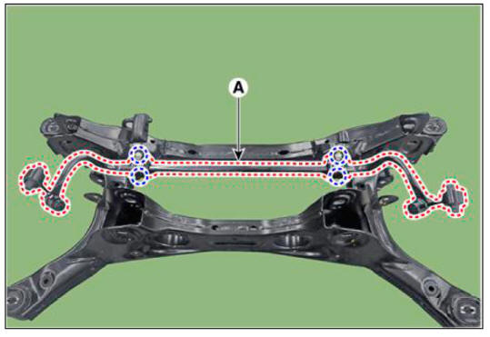
- Remove the rear stabilizer bar (A) after loosening the mounting bolts.
Tightening torque : 53.9 - 63.7 N.m (5.5 - 6.5 kgf.m, 39.8 - 47.0 lb-ft)
Inspection
- Check the rear stabilizer bar for deformation.
- Check the rear stabilizer link ball joint for damage.
Installation
- To install, reverse the removal procedures.
- Check the alignment.
(Refer to Suspension System - "Alingment")
READ NEXT:
 Tire Rotation
Tire Wear
WARNING
Using tires and wheel other than the recommended sizes could cause
unusual handling characteristics
and poor vehicle control, resulting in a serious accident.
Measure the tread depth of the tires.
Tread depth limit : 1.6
Tires_Wheels - Installation
Installation
Apply tire soap or lubrication to the top and bottom tire beads.
WARNING
When changing the wheel, do not reuse the snap-in type TPMS sensor.
To fit the bottom bead, position the valve at the 5 o'clock position
rela
SEE MORE:
Introduction of Quick Brake Warning System (ESS)
Description
In case of quick brake by driver, the brake lamp or turn signal is blinked to
warn against the vehicle at rear.
Basic function (Blinking the brake lamp/emergency lamp)
Operation condition : In case of quick brake or opera
System maintenance
Cabin air filter
[A] : Outside air, [B] : Recirculated air
[C] : Cabin air filter, [D] : Blower
[E] : Evaporator core, [F] : Heater core
The cabin air filter is installed behind
the glove box. It filters the dust or other
pollutants that en
Information
- Home
- Hyundai Tucson - Fourth generation (NX4) - (2020-2023) - Owner's Manual
- Hyundai Tucson - Fourth generation (NX4) - (2020-2023) - Workshop Manual
