Hyundai Tucson: Pedal Type
Front cable
- Disconnect the (-) batteiy terminal.
- Release the parking brake.
- Remove the crash pad lower panel.
(Refer to Body - "Crash Pad Lower Panel")
- Remove the Integrated Central Control Unit (ICU).
(Refer to Body Electrical System - "Relay Box (Passenger Compartment)")
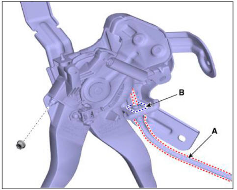
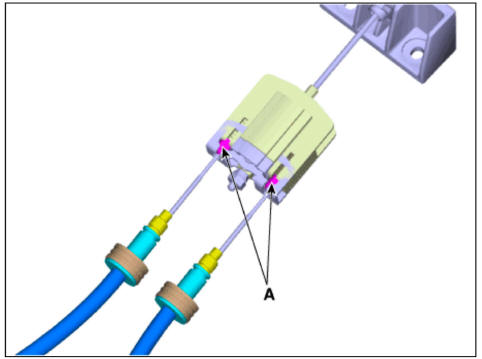
- Separate the parking brake cable (A) by removing the nut and retaining clip (B).
- Remove the floor console assembly.
(Refer to Body - "Floor Console Assembly")
- Remove the front parking brake cable bracket (A) by removing the bolts and clip.
Tightening torque : 19.6 - 29.4 N m (2.0 - 3.0 kgfm, 14.5 - 21.7 lb ft)
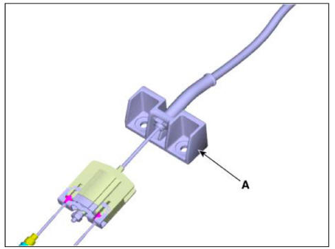
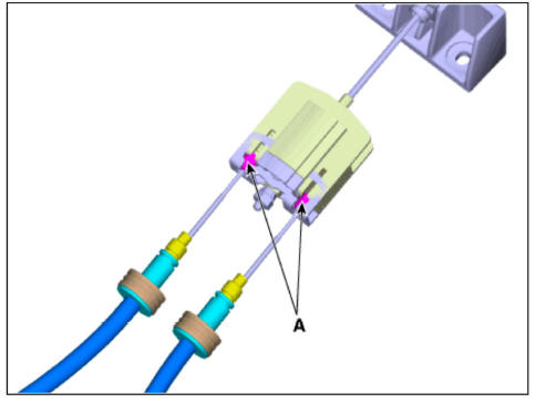
- Remove the cable retainer and remove the parking brake cable (A).
- Remove the mounting bolts and remove the parking brake cable (A).
Tightening torque : 3.9 - 5.9 N m (0.4 - 0.6 kgfrn, 2.8 - 4.3 lb ft)
Rear cable
- Disconnect the (-) batteiy terminal.
- Release the parking brake.
- Remove the floor console assembly.
(Refer to Body - "Floor Console Assembly")
- Remove the cable retainer and remove the parking brake cable (A).
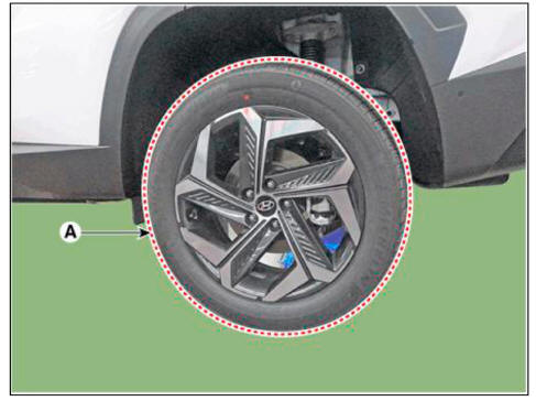
- Remove the rear wheel and tire (A) from the rear hub.
Tightening torque : 107.9 - 127.5 N.m (11.0-13.0 kgf.m, 79.6 - 94.0 lb-ft)
WARNING
Be careful not to damage the hub bolts when removing the rear wheel and tire (A).
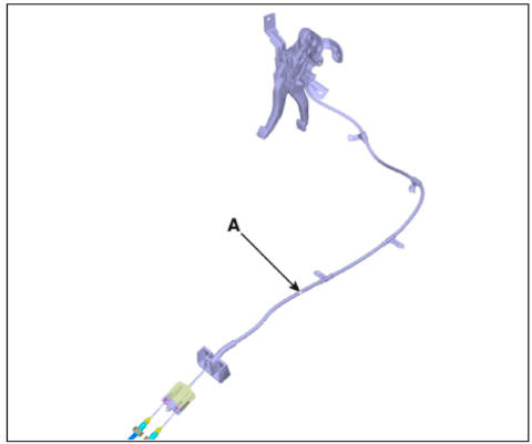
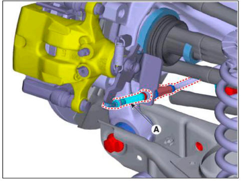
- Remove the parking brake cable (A), after removing the clip.
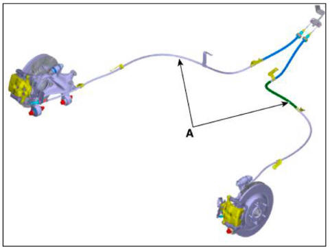
- Remove the mounting bolts and remove the parking brake cable (A).
Tightening torque : 19.6 - 29.4 N m (2.0 - 3.0 kgfm, 14.5 - 21.7 lb ft)
Installation
- Install in the reverse order of removal.
- After the installation, check the operation status of the parking brake and brake switch.
Adjustment
- To fit the cable, follow one of these procedures
- Apply a parking brake fully more than 3 times
- With full operation, hold the parking brake for 1 to 2 hours.
- After fitting the cable, adjust the adjustment nut so that the stroke is 5 - 6 notch when operating the pedal at 30kgf.
WARNING
For the BIR type, adjust the adjustment nut of the lever assembly so
that the sum of the O / P lever on
the rear caliper side and the stopper (LH / RH) angle is within 3.0 mm (0.11
in). 
- Make sure that there is no gap between adjustment nut and clip after adjusting the parking brake.
- Make sure that the brakes are not drag.
- Check whether the wheel operates smoothly.
- Perform driving test.
Description
The electronic parking brake (EPB) is different from existing parking systems which operated with the brake pedal or the lever type. The EPB system sends the signal to the ECU when a driver operates the EPB switch. The ECU operates the EPB actuator composed with motor gears. The braking power is caused by occurs when the motor pulls the cable connected the brake system.
The EPB ECU is one of the parts of EPB system. It perceives the signal of the various sensor of system, executes a self diagnosis, controls EPB system with the logic.
READ NEXT:
 Main Function
Static Braking Mode
The operation and the cancellation at the stop condition of the vehicle
(1) The operation condition: Pull the EPB switch irrespective of the brake
pedal pressed condition.
(Pull).
The Vehicle speed <= 3kph
(2
Electronic Parking Brake (EPB)
Components
ESC Control Module (HECU)
EPB Switch
Electronic Parking Brake (EPB) actuator
Circuit Diagram
Electronic Parking Brake (EPB)- Removal
WARNING
Be careful not to damage the parts located under the vehicle (floor
SEE MORE:
Evaporative Emission Control System - Removal
Removal
WARNING
Be careful not to damage the parts located under the vehicle (floor
under cover, canister, fuel tank)
when raising the vehicle using the lift.
(Refer to General Information - "Lift and Support Points")
Turn
Engine Mechanical System - Installation
Installation
Install in the reverse order of removal.
Disassembly
Remove the M-terminal nut (A) on the magnetic switch assembly (B).
After loosening the screws (A), remove the magnetic switch assembly.
Remove the throug
Information
- Home
- Hyundai Tucson - Fourth generation (NX4) - (2020-2023) - Owner's Manual
- Hyundai Tucson - Fourth generation (NX4) - (2020-2023) - Workshop Manual
