Hyundai Tucson: Outside Rear View Mirror - Installation
Hyundai Tucson - Fourth generation (NX4) - (2020-2023) - Workshop Manual / Body Electrical System / Lighting System / Outside Rear View Mirror - Installation
Outside Rear View Mirror
Installation
- Install the outside rear view mirror and connect the connector.
Tightening torque : 6.9 - 10.8 N.m (0.7 - 1.1 kgf.m, 5.0 - 8.0 lb-ft)
- Connect the negative (-) batteiy terminal.
Front/Rear Turn Signal Lamp
- Install the front/rear turn signal lamp.
- Install the front/rear bumper cover.
- Connect the negative (-) batteiy terminal.
Removal
Rear Personal Lamp
- Disconnect the negative (-) battery terminal.
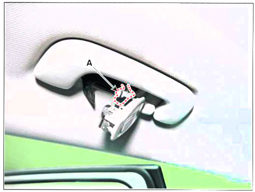
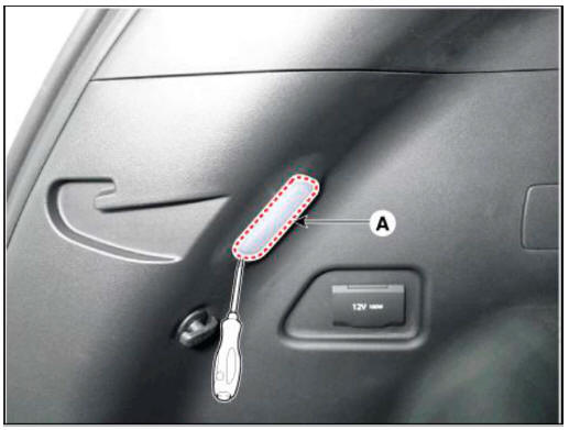
- Remove the rear personal lamp (A).
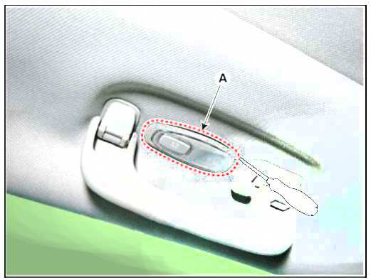
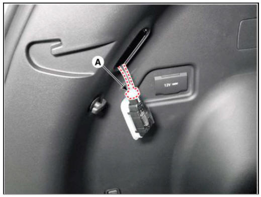
- Disconnect the rear personal lamp connector (A).
Room Lamp (Without sunroof)
- Disconnect the negative (-) battery terminal.
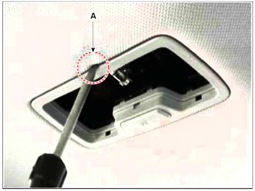
- Detach the lamp lens (A) from the room lamp with a flat-tip screwdriver.
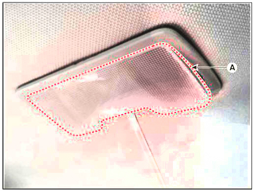
- If it is necessary replace the room lamp bulb (A).
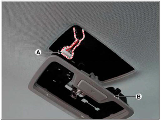
- Loosen the mounting screws and remove the room lamp (B).
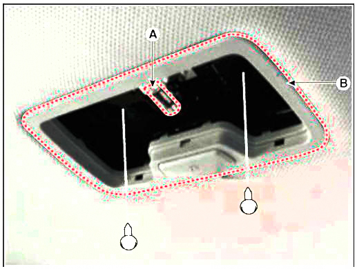
- When using the tool to remove the lamp, pay attention to the direction of tool insertion (A)
- Be careful not to break the room lamp when inserting the tool in the opposite direction.
- Disconnect the room lamp connector (A) and remove the room lamp (B) from the roof trim.
Installation
Room Lamp (Without sunroof)
- Connect the connector and install the lamp.
- Install the room lamp lens.
- Connect the negative (-) battery terminal.
Rear Personal Lamp
- Connect the connector and install the lamp.
- Connect the negative (-) battery terminal.
Removal
- Disconnect the negative (-) battery terminal.
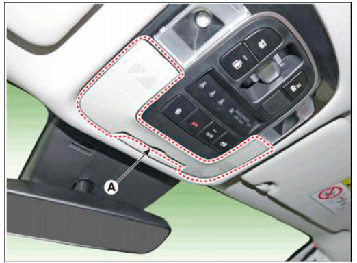
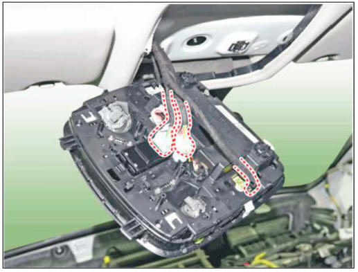
- Remove the overhead console cover (A).
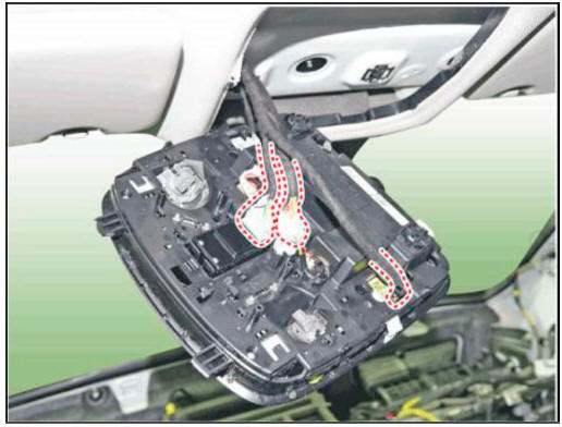
- Remove the mounting screws.and then remove the overhead console (A).
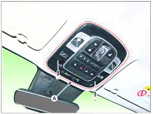
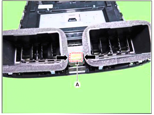
- Remove the overhead console after disconnect the connector (A).
Installation
- Install the overhead console lamp after connecting the connector.
- Connect the negative (-) battery terminal.
Inspection
- Remove the overhead console lamp assembly then check for continuity between terminals. If the continuity is not as specified, replace the map lamp switch.
Removal
- Disconnect the negative (-) battery terminal.
- Remove the front monitor.
(Refer to AVN System - "Front Monitor")
- Remove the hazard switch (A).
Installation
- Install the hazard switch.
- Install the front monitor.
- Connect the negative (-) battery terminal.
Removal
- Disconnct the negative (-) batteiy terminal.
- Remove the crash pad lower panel.
(Refer to Body - "Crash Pad Lower Panel")
- Loosen the mounting screw and remove the crash pad garnish LH (A).
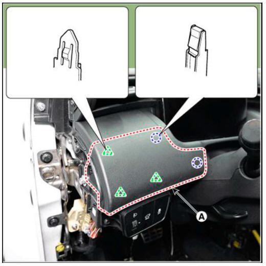
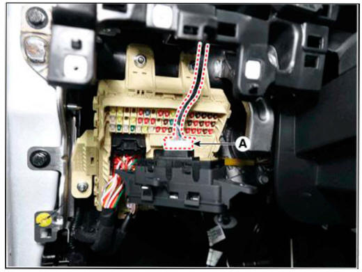
- Loosen the mounting screws and remove the crash pad lower switch assembly (A).

- Disconnect the crash pad lower switch connector (A).
Installation
- Instahh the crash pad lower switch
- Install the crash pad garnish LH.
- Install the crash pad lower panel.
- Connect the negative (-) terminal
Removal
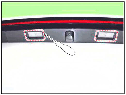
- Disconnct the negative (-) batteiy terminal.
- Using a flat-tip screwdriver and remove the license lamps.
Installation
- Install the bulb.
- Install the license lamp lens.
Removal
- Disconnect the negative (-) battery terminal.
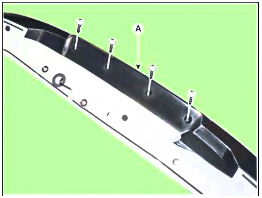
- Remove the rear spoiler.
(Refer to Body - "Rear Spoiler")
- Remove the high mounted stop lamp assembly (A) after loosening screws (4EA).
Installation
- Install the high mounted stop lamp.
- Install the rear spoiler.
- Connect the negative (-) battery terminal.
Removal
- Disconnect the negative (-) battery terminal.
- Using a flat-tip screwdriver and remove the luggage room lamp (A).
- Disconnect the luggage room lamp connector (A).
Installation
- Connect the luggage room lamp connector.
- Install the luggage room lamp.
- Connect the negative (-) battery terminal.
Removal
- When removing with a flat-tip screwdriver or remover, wrap protective tape around the tools to prevent damage to components.
- Put on gloves to prevent hand injuries.
- Take care not to bend or scratch the bumper cover and panels.
READ NEXT:
 Rear Outside Combination Lamp
Disconnect the negative (-) battery terminal.
Loosen the mounting bolts then remove the outside rear combination lamp
(A).
Disconnect the rear combination lamp connector (A).
Remove the bulb after turning it in the counter
Rear Occupant Alert
Description
The system detects the passenger in the vehicle and prevents the driver from
getting off the vehicle with the passenger in the
1st warning: If you open the driver's door after you open and then close
the rear passenger and t
SEE MORE:
Driveshaft Assembly- Removal
Components
Front driveshaft (LH)
Inner shaft bearing bracket
Front driveshaft (RH)
Removal
WARNING
When lifting a vehicle using a lift, be careful not to damage
the lower parts of the vehicle (floor under cover,
fuel filter,
DCT (Dual Clutch Transmission) System (SBC) - Installation
Installation
To install, reverse the removal procedure.
WARNING
Matters that require attention when installing the dual clutch
transmission (DCT) to engine
l)Check the pilot bearing (B) and external damper (A) on the side of
engine for a
Information
- Home
- Hyundai Tucson - Fourth generation (NX4) - (2020-2023) - Owner's Manual
- Hyundai Tucson - Fourth generation (NX4) - (2020-2023) - Workshop Manual
