Hyundai Tucson: Heater - Replacement
- Disconnect the negative (-) battery terminal.
- Recover the refrigerant with a recovery/recycling/charging station.
(Refer to Air conditioning System - "Repari procedures")
- When the engine is cool, drain the engine coolant from the radiator.
(Refer to Engine Mechanical System - "Coolant")
- Remove the cowl top cover.
(Refer to Body (Interior and Exterior) - "Cowl Top Cover")
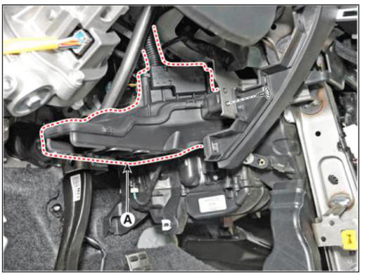
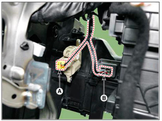
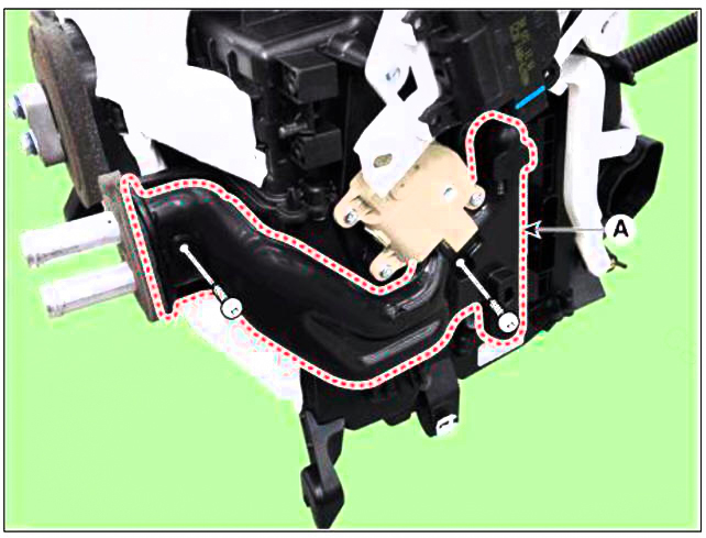
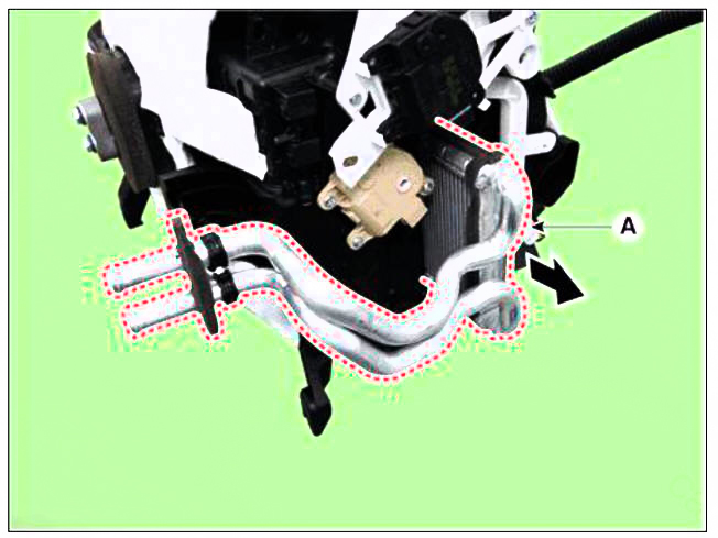
- Loosen the mounting nut and separate the expension valve cover (A).
Tightening torque : 7.8 - 11.8 N.m (0.8 - 1.2 kgf.m, 5.8 - 8.7 lb-ft)
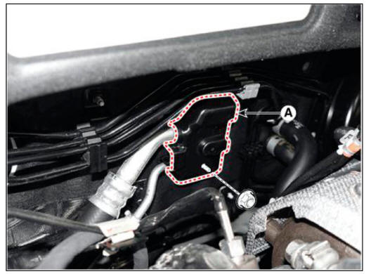
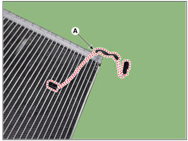
- Loosen the mounting bolts and separate the expension valve (A) from the evaporator core.
Tightening torque : 21.6 - 32.4 N.m (2.2 - 3.3 kgf.m, 15.9 - 23.9 lb-ft)
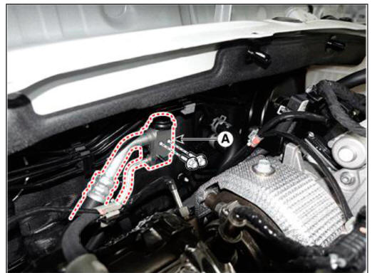
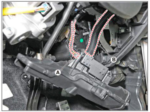
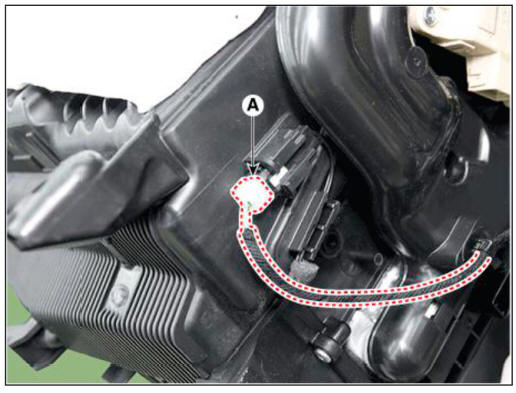
- Separate the heater hose (A).
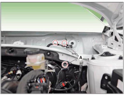
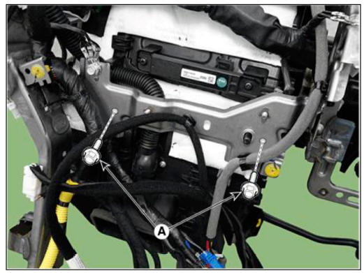
- Loosen the cowl cross bar assembly mounting bolts (A).
Tightening torque : 16.7 - 25.5 N.m (1.7 - 2.6 kgf.m, 12.3 - 18.8 lb-ft)
- Remove the front seat assembly.
(Refer to Body (Interior and Exterior) - "Front Seat Assembly")
- Remove the floor console assembly.
(Refer to Body (Interior and Exterior) - "Floor Console Assembly")
- Remove the front pillar trim.
(Refer to Body (Interior and Exterior) - "Front Pillar Trim")
- Remove the cowl side trim.
(Refer to Body (Interior and Exterior) - "Cowl Side Trim")
- Remove the crash pad lower panel.
(Refer to Body (Interior and Exterior) - "Crash Pad Lower Panel")
- Remove the steering column shroud lower panel.
(Refer to Body (Interior and Exterior) - "Steering Column Shroud Panel")
- Remove the steering wheel.
(Refer to Steering System - "Steering Wheel")
- Remove the multifunction switch.
(Refer to Body Electrical System - "Multifunction Switch")
- Lower the steering column after loosening the mounting bolts.
(Refer to Steering System - "MDPS PowerPack Assembly")
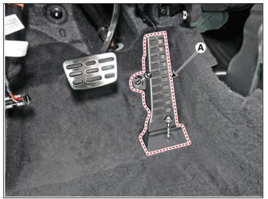
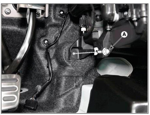
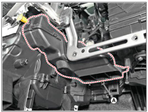
- Loosen the mounting bolt and nut. remove the accelerator pedal module (A).
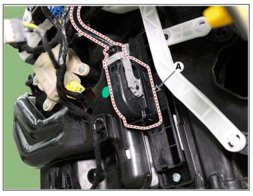
- Press the lock pin, separate the accelerator pedal connector (A).
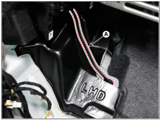
- Remove the rear air duct (B) and then separate the floor carpet (A) backwards.
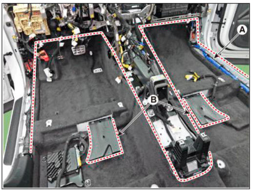
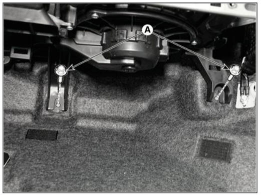
- Loosen the mounting nuts and remove the rear heating duct (A).
- Loosen the mounting nuts and remove the console duct (A).

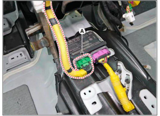
- Disconnect the airbag control module(SRSCM) connector (A).
- Disconnect the passenger compartment junction box connectors (A).
- Disconnect the multi box connectors (A).
Driver's
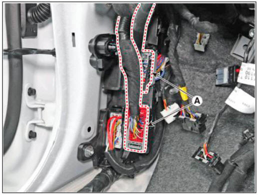
Passenger's
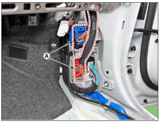
- Disconnect the connector (A) and the mounting wiring fasteners in the front pillar.
Driver's
Passenger's
- Remove the drain hose (A).
- Remove the lower mounting bolt of the blower unit.
Tightening torque : 3.9 - 5.9 N.m (0.4 - 0.6 kgf.m , 2.9 - 4.3 lb-ft)
Driver's
Passenger's
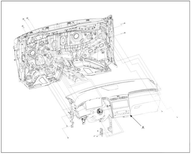
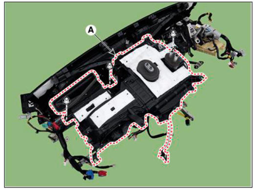
- After loosening the bolts and nuts remove the crash pad and heater & blower unit assembly (A) together.
- Remove the DC DC converter.
(Refer to Engine Electrical System - "DC DC converter")
- Remove the IBU.
(Refer to Body Electrical System - "Integrated Body Control Unit (IBU)")
- Remove the heater control unit.
(Refer to Controller - "Heater Control Unit")
- Remove the shower duct.
LH
(1) Loosen the mounting screw, remove the shower duct (A).
(2) Disconnect the PM sesnor connector (A) and hose (B).
RH
(3) Loosen the mounting screw, remove the shower duct (A).
- Disconnect the heater and blower unit connectors.
(1) Disconnect the PTC heater connector (A).
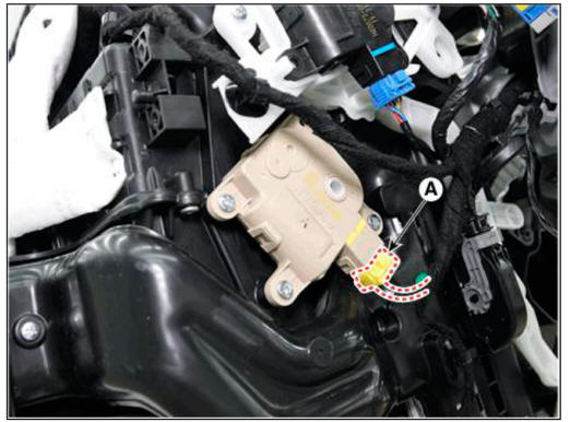
(2) Disconnect the driver's temperature control actuator connector (A).
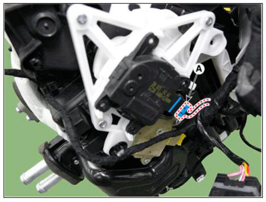
(3) Disconnect the mode control actuator connector (A).
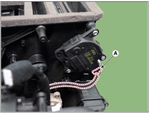
(4) Disconnect the auto defogging actuator connector (A).
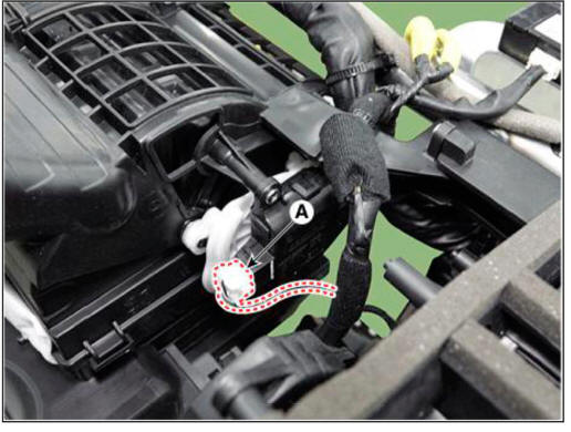
(5) Disconnect the intake actuator connector (A).
(6) Disconnect the passenger's temperatur actuator connector (A) and power mosfet connector (B).
(7) Disconnect the evaporator sensor connector (A).
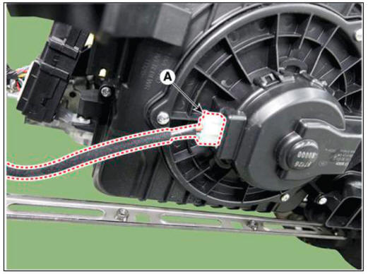
(8) Disconnect the blower motor connector (A).
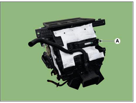
- Loosen the heater & blower unit mounting bolt (A).
Tightening torque : 3.9 - 5.9 N.m (0.4 - 0.6 kgf.m , 2.9 - 4.3 lb-ft)
- Loosen the mounting nuts and remove the heater & blower unit (A) from the crash pad.
Tighteuiug torque : 3.9 - 5.9 N.m (0.4 - 0.6 kgf.m , 2.9 - 4.3 lb-ft)
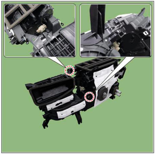
- Loosen the mounting screw and separate the heater unit (A).
Tighteuiug torque : 3.9 - 5.9 N.m (0.4 - 0.6 kgf.m , 2.9 - 4.3 lb-ft)
- Install in the reverse order of removal.
WARNING
- Make sure that each of the assembly components operates properly.
- Replace any damaged clips (or pin-type retainers).
Heater - Replacement
- Disconnect the negative (-) battery terminal.
- Remove the heater and blower assembly.
(Refer to Heater - "Heater Unit")
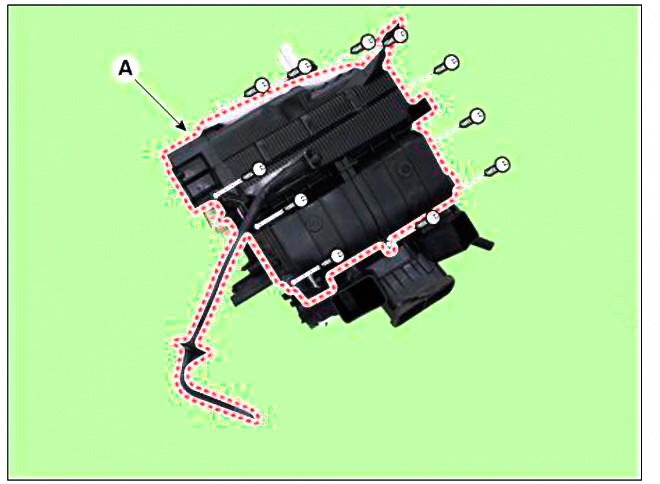
- Loosen the mounting screws and remove the heater core cover (A).
- Separate the heater core (A) from the heater unit.
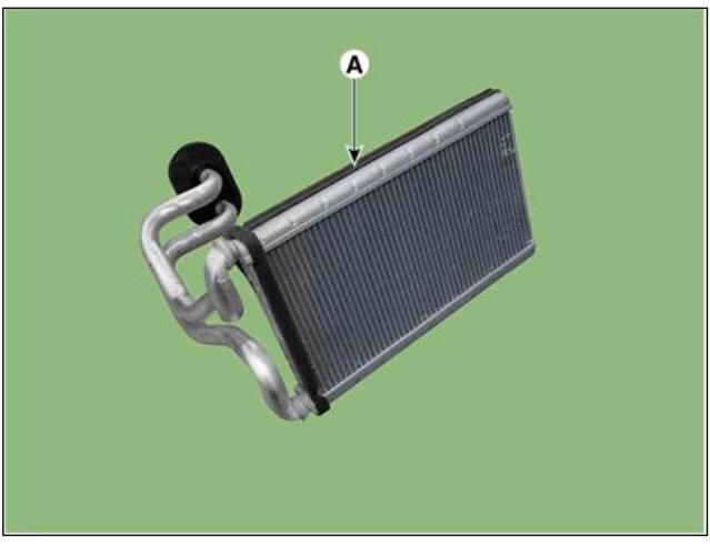
- Install in the reverse order of removal.
WARNING
- Refill the cooling system with engine coolant.
- Do not interchange the inlet and outlet heater hoses and install the hose clamps securely.
- Make sure that there is no air leakage.
- Charge the system and test its performance.
Replacement
- Disconnect the negative (-) battery terminal.
- Remove the heater core.
(Refer to Heater - "Heater Core")
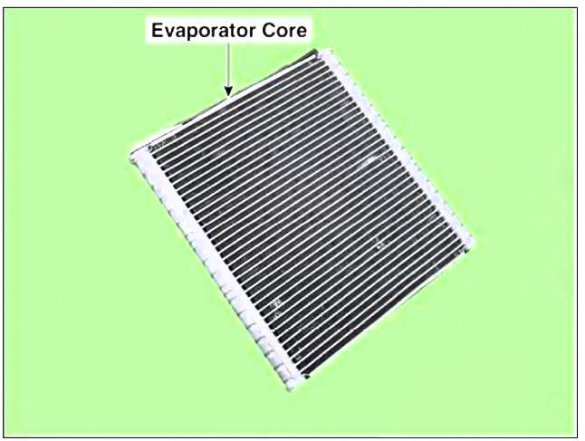
- Loosen the mounting screws and remove the evaporator core cover (A).
- Remove the evaporator core (A) from the heater unit.
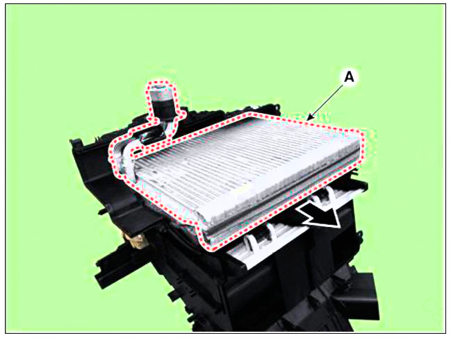
- Remove the evaporator temperature sensor (A) from the evaporator core.
- Install in the reverse order of removal.
WARNING
- If you're installing a new evaporator core, add refrigerant oil (PAG OIL).
- Replace the O-rings with new ones at each fitting, and apply a thin coat of refrigerant oil before installing them. Be sure to use the right O-rings for R-134a or R-1234yf to avoid leakage.
- Immediately after using the oil, replace the cap on the container, and seal it to avoid moisture absorption.
- Do not spill the refrigerant oil on the vehicle; it may damage the paint; if the refrigerant oil contacts the paint, wash it off immediately.
- Apply sealant to the grommets.
- Make sure that there is no air leakage.
- Charge the system and test its performance.
- Do not interchange the inlet and outlet heater hoses and install the hose clamps securely.
- Refill the cooling system with engine coolant.
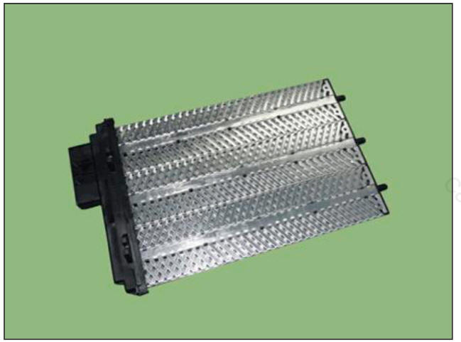
Description
The PTC (Positive Temperature Coefficient) heater is installed at the exit or the backside of the heater The PTC heater is an electric heater using a PTC element as an auxiliary heating device that supplements deficiency of interior heat source in highly effective diesel engine. The electric heater heats up the interior by directly heating the air that passes through the heater. The name itself implies that the element has a proportional resistance change sensitive to temperature.
Operation Principle
ECM outputs a PTC ON signal and operates PTC relay 1. Then the heater controller operates PTC relay 2 with an interval of 15 seconds.
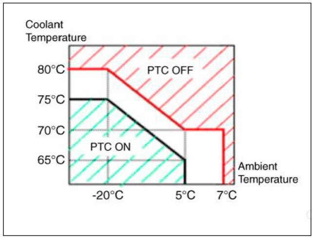
Operating Condition
PTC heater operates according to the following conditions :
- Battery voltage : 13V or above
- Engine : Running
- Ambient temperature and coolant temperature
READ NEXT:
 Heater - Inspection
Operating Logic Test (Manual only)
Inspect the PTC operation with the confirmation logic below :
Entering
(1) Set the mode to FLOOR.
(2) Set the temperature to MAX HOT.
(3) Turn off the blower switch.
(4) Press the intake (recirculat
Driver side temperature control actuator / Passenger side temperature
control actuator
Component Location
Driver side temperature control actuator
Passenger side temperature control actuator
Inspection
Turn the ignition switch OFF.
Disconnect the temperature control actuator connector.
Verify that the temperature c
Mode control actuator
Components Location
Mode control actuator
Inspection
Turn the ignition switch OFF.
Disconnect the mode control actuator connector.
Verify that the mode control actuator operates to the defrost mode when
connecting 12V to termina
SEE MORE:
ESC Control unit (HECU) - Adjustment
Adjustment
Perform diagnostic procedure by using diagnostic device as shown below :
Connect self-diagnosis connector (16pins) located under the driver side
crash pad to self-diagnosis device, and then torn the
self-diagnosis device after ke
Glass Adjustment
WARNING
Check the glass run channel for damage or deterioration, and replace
it if necessary.
Remove the front door trim.
(Refer to Front Door - "Front Door Trim")
Lower the glass by operating the power window switch until the gl
Information
- Home
- Hyundai Tucson - Fourth generation (NX4) - (2020-2023) - Owner's Manual
- Hyundai Tucson - Fourth generation (NX4) - (2020-2023) - Workshop Manual
