Hyundai Tucson: Gear acmator assembly
Components
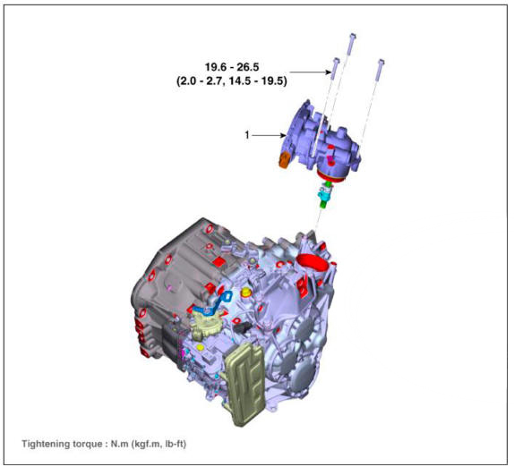
- Gear acmator assembly
Specification
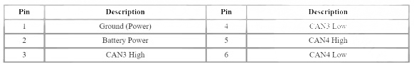
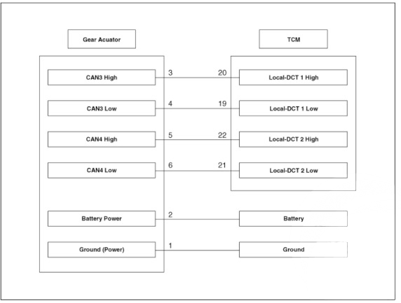
Connector and Terminal Function
Circuit Diagram
Inspection
- The DCT system can be more quickly diagnosed for troubles by using the vehicle diagnostic system (diagnostic tool). (Refer to DTC guide) diagnostic tool provides the following information.
1) Self diagnosis : Inspects and displays diagnostic trouble code (DTC)
2)CAN signals: Checks the system input/output value status
3)Forced operation : Checks the system operating stams
4)Additional function : Controls system options, zero point adjustment and other functions
Removal
- Turn ignition switch OFF and disconnect the negative (-) battery cable.
- Remove the air cleaner assembly and air duct.
(Refer to Engine Mechanical System - "Air cleaner")
- Remove the ECM.
(Refer to Engine Control / Fuel System - "Engine Control Module (ECM)")
- Remove the battery and battery tray.
(Refer to Engine Electrical System - "Battery")
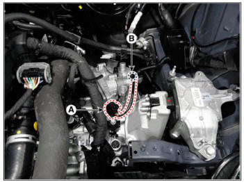
- Disconnect the gear actuator connector (A).
- Loosen the gear actuator wiring bracket mounting bolts (B).
Tightening torque : 9.8- 11.8 N.m (1.0- 1.2 kgf.m. 7.2 - 8.7 lb-ft)
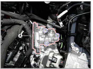
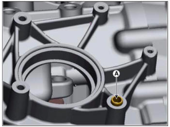
- Loosen the bolts and then removing the gear actuator (A).
Tightening torque : 19.6 - 26.5 N.m (2.0 - 2.7 kgf.m, 14.5 - 19.5 lb-ft)
Installation
- To install, reverse the removal procedure.
WARNING
- Check the details below before installing the gear acmator assembly.
1)Check that the gear acmator is placed in the "neutral" state.
2)Check the assembled state of the O-rings (A).
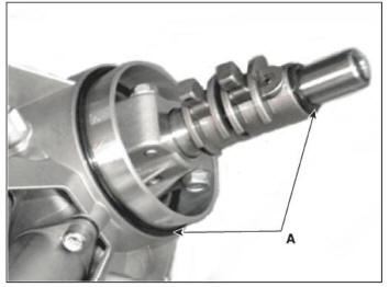
3)Apply gear oil to the surface of O- rings.
4)Check the assembled state of the dowel pins (A).
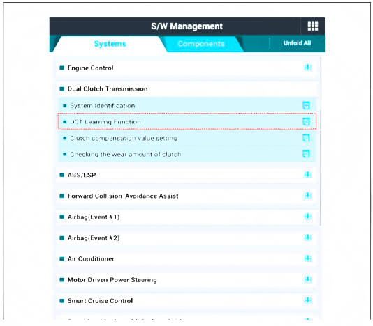
- Perform the clutch touch point learning procedure using the diagnostic tool after replacing the clutch acmator assembly.
READ NEXT:
 Gear acmator assembly- Description
Components location : DCT (Dual Clutch Transmission)
Function
The input shaft speed sensor is important in that it detects the input shaft
RPM and sends this
information to the Transmission Control Module (TCM).
It provides important
Inhibitor switch/ Manual control lever
Components
Inhibitor switch
Manual control lever
Fault Diagnosis
Fault Diagnosis for Symptom
Specifications
Signal Code Table
Inspection
WARNING
Thoroughly check connectors for looseness, poor connection, bending,
cor
Inhibitor switch/ Manual control lever- Removal
Turn ignition switch OFF and disconnect the batteiy negative (-)
terminal.
Make sure vehicle does not roll before setting shift lever to "N"
position.
Remove the air cleaner assembly and air duct.
(Refer to Engine Mechanical
SEE MORE:
General Information
Troubleshooting
Specifications
Tightening Torque
Special Service Tools
Air Cleaner Assembly
Removal and
Installation
Disconnect the battery negative terminal.
Disconnect the air flow sensor (AFS) connector (A).
Remove the air duct (A).
Disconnect the RCV hose (A).
Remove the air cleaner assembly
Tight
Information
- Home
- Hyundai Tucson - Fourth generation (NX4) - (2020-2023) - Owner's Manual
- Hyundai Tucson - Fourth generation (NX4) - (2020-2023) - Workshop Manual
