Hyundai Tucson: Front Brake Pad
- Loosen the wheel nuts slightly.
Raise the vehicle, and make sure it is securely supported.
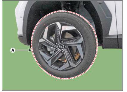
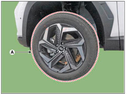
- Remove the front wheel and tire (A) from front hub
WARNING
Be careful not to damage the hub bolts when removing the front wheel and tire (A).
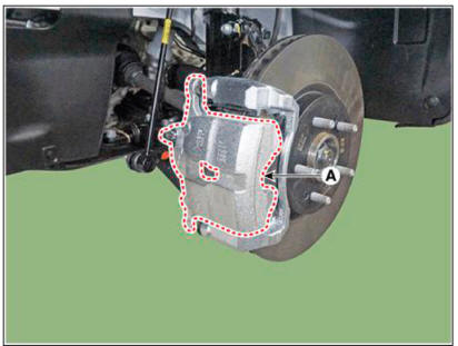
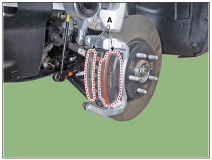
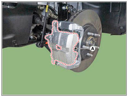
- Up the brake caliper body (A) by loosening the guided rod bolt.
Tightening torque : 37.3 - 41.2 N.m (3.8 - 4.2 kgf.m, 27.5 - 30.4 lb-ft)
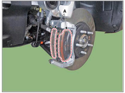
- Remove the brake pad (A).
- Replace the pad liner (A) with a new one.
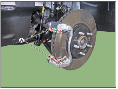
WARNING
Brake apply a small amount of grease to the areas marked with "X" on both ends of the new product.
(Be careful as excessive coating may cause noise due to contamination on the
disk or friction material.) 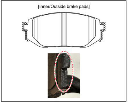
- Replace the brake pad (A) with a new one.
WARNING
When replacing the brake pads, replace both the brake pads (A), pad
retainer (B), and pad shim (C).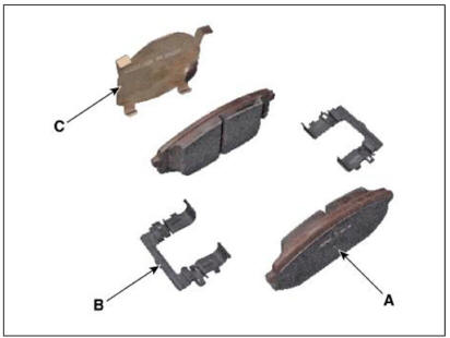
- Use a SST (09581-11000) when installing the brake caliper assembly.
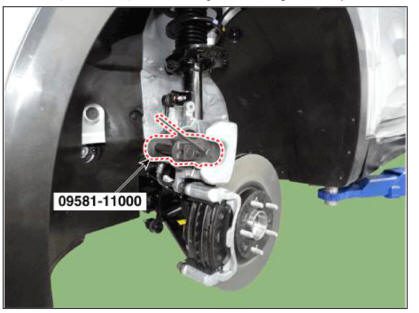
- Install the caliper body (A) then tighten the guide rod bolt.
Tightening torque : 21.6-31.4 N.m (2.2-3.2 kgf.m, 15.9-23.1 lb-ft)
- Install the front wheel and tire (A).
Tightening torque : 107.8 - 127.4 N.m (11.0 - 13.0 kgf.m, 79.5 - 94.0 lb-ft)
READ NEXT:
 Rear Brake Pad
After installing the rear caliper, perform "Brake Pad Replacement Mode"
using the self-diagnosis. EPB Apply
Select C2 (Release) on the screen below.
After disassembling/assembling the caliper body or replacing
Brake Pedal
Components
Brake member assembly
Stop lamp switch
Brake pedal arm assembly
Brake pedal pad
Schematic Diagram
System circuit diagram
Terminal Function
Adjustment
Turn ignition switch OFF and disconnect the negat
Brake Pedal - Removal
Turn ignition switch OFF and disconnect the negative (-) batteiy cable.
Remove the crash pad lower panel.
(Refer to Body - "Crash Pad Lower Panel")
Disconnect the stop lamp switch connector (A).
Pull the locking plate (A)
SEE MORE:
Cylinder Head Assembly- Installation
The hardening sealant located on the upper area between timing chain
cover and cam carrier, cylinder head
cover should be removed before assembling cylinder head cover.
Install the cylinder head cover.
(1) Install the new gasket.
WARNIN
CMF Battery
Description
The CMF (Closed Maintenance Free) battery is, as the name implies, totally
maintenance free and has
no removable battery cell caps.
The CMF (Closed Maintenance Free) battery does not require water replenishment
for the repair.
Information
- Home
- Hyundai Tucson - Fourth generation (NX4) - (2020-2023) - Owner's Manual
- Hyundai Tucson - Fourth generation (NX4) - (2020-2023) - Workshop Manual
