Hyundai Tucson: Front Axle Assembly
Components
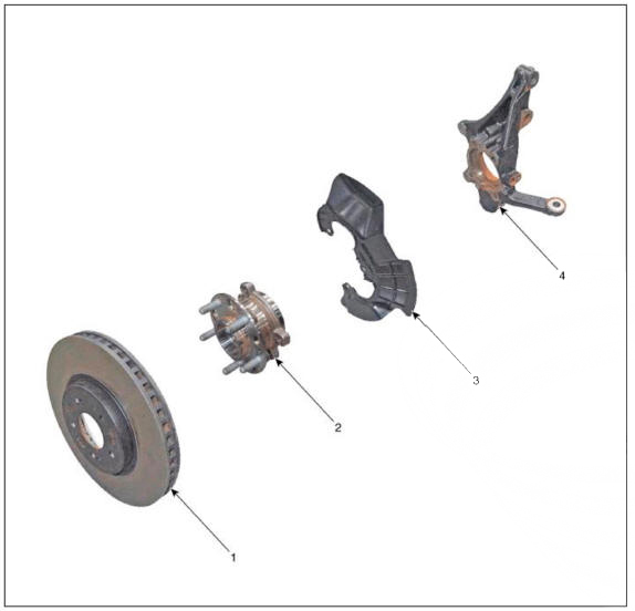
- Front brake disc
- Front hub assembly
- Dust cover
- Front knuckle
Removal
WARNING
- When lifting a vehicle using a lift, be careful not to damage the lower parts of the vehicle (floor under cover, fuel filter, fuel tank, canister).
(Refer to General Information - "Lift Point")
- Loosen the front wheel nuts slightly.
Raise the vehicle, and make sure it is securely supported.
- Remove the front wheel and tire.
(Refer to Suspension System - "Wheel")
- Remove the front brake caliper.
(Refer to Brake System - "Front Disc Brake")
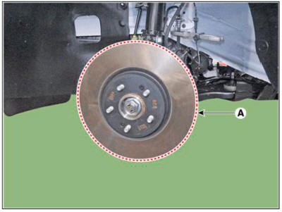
- Remove the front brake disc (A) after loosening the screw.
Tightening torque :
4.9 - 5.9 N.m (0.5 - 0.6 kgf.m, 3.6 - 4.3 lb-ft)
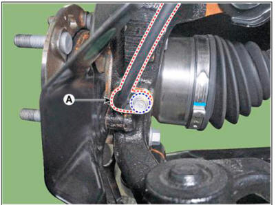
- Disconnect the wheel speed sensor (A) from the knuckle after loosening the mounting bolt.
Tightening torque : 6.9 - 10.8 N.m (0.7 -1.1 kgf.m. 5.1 - 8.0 lb-ft)
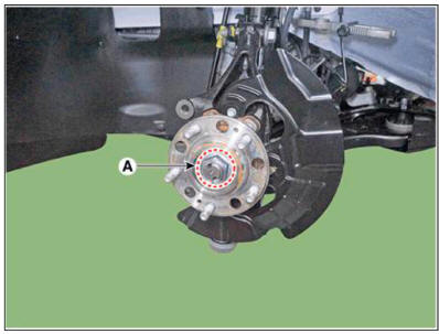
- Loosen the caulking nut (A).
Tightening torque : 294.2 - 313.8 N.m (30.0 - 32.0 kgf.m, 217.0 - 231.5 lb-ft)
WARNING
- The driveshaft lock nut (A) should be replaced with new ones.
- After installation driveshaft lock nut, stake the lock nut
using a chisel and hammer as shown in the
illustration below.
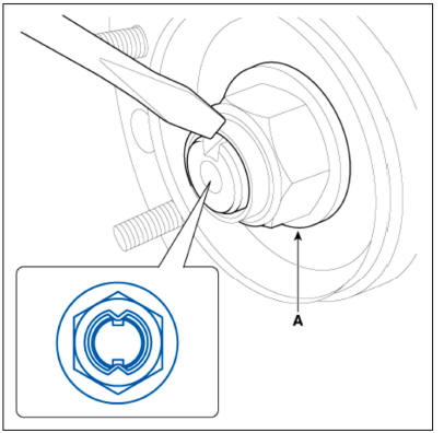
Caulking depth : 1.5 mm (0.591 in.)
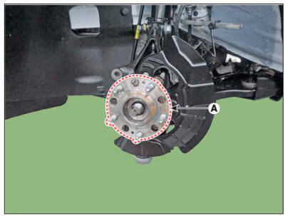
- Remove the front hub bearing (A) after loosening the mounting bolts.
Tightening torque : 78.5 - 98.1 N.m (8.0 - 10.0 kgf.m, 57.9 - 72.3 lb-ft)
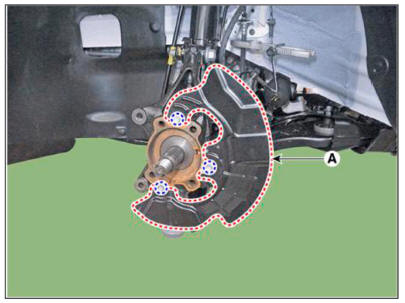
- Remove the dust cover (A).
Tightening torque : 3.9 - 5.9 N.m (0.4 - 0.6 kgf.m, 2.9 - 4.3 lb-ft)
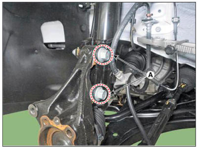
- Loosen the front strut assembly mounting bolts and nuts (A) from the front axle.
Tightening torque : 156.9- 176.5 N.m( 16.0- 18.0 kgf.m, 115.7-130.2 lb-ft)
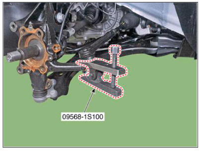
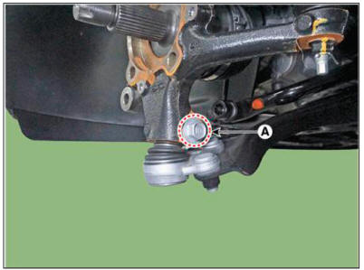
- Loosen the tie rod end ball joint nut (A).
Tightening torque: 98.0 - 117.6 N.rn (10.0 - 12.0 kgf.m, 72.3 - 86.7 lb-ft)
- Remove the tie rod end ball joint using the SST (09568-1S100).
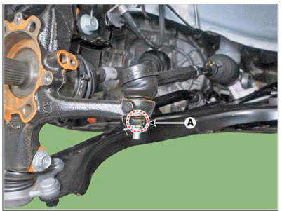
- Loosen the front lower arm mounting bolt and nut (A).
Tightening torque: 98.0 - 117.6 N.m (10.0 - 12.0 kgf.m, 72.3 - 86.7 lb-ft)
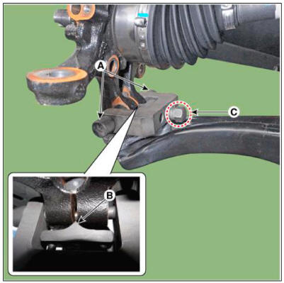
- Remove the lower arm from the knuckle by using the SST (09568-4R100).
(1) Install the support bolt (A) from lower arm bolt hole.
(2) Install the support body (B) from front axle.
(3) Tighten the bolt (C).
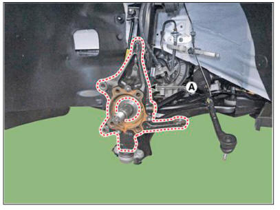
- Remove the front knuckle (A).
Inspection
- Check the hub for cracks and the splines for wear.
- Check the brake disc for scoring and damage.
- Check the knuckle for cracks.
- Check the bearing for cracks or damage.
Installation
- To install, reverse the removal procedures.
- Check the alignment.
(Refer to Suspension System - "Alingment")
READ NEXT:
 Driveshaft Assembly- Removal
Components
Front driveshaft (LH)
Inner shaft bearing bracket
Front driveshaft (RH)
Removal
WARNING
When lifting a vehicle using a lift, be careful not to damage
the lower parts of the vehicle (floor under cover,
fuel filter,
Driveshaft Assembly- Installation
Installation
To install, reverse the removal procedures.
Check the alignment.
(Refer to Suspension System - "Alingment")
Removal
Remove the front drive shaft.
(Refer to Driveshaft Assembly - "Front Driveshaft")
SEE MORE:
Safe exit warning (SEW)
After the vehicle stops, when an
approaching vehicle from the rear area is
detected as soon as a passenger opens
a door, Safe Exit Warning will warn the
driver with a warning message and
an audible warning to help prevent a
collision.
CAUT
Glass step alignment
Alignment
Perform considerable step alignment after replacing movable glass (A).
Perfrom height adjustment releasing screw (A) a bit.
WARNING
Be careful not to damage screws.
Remove the decoration cover (A).
Information
- Home
- Hyundai Tucson - Fourth generation (NX4) - (2020-2023) - Owner's Manual
- Hyundai Tucson - Fourth generation (NX4) - (2020-2023) - Workshop Manual
