Hyundai Tucson: EPS Type Recognition
WARNING
When missing the EPS Type Recognition, occure a problem with motor driven power steering performance
EPS Type Recognition procedures
- Connect self-diagnosis connector(16pins) located in the lower of driver side crash pad to self-diagnosis device.
- Turn the self-diagnosis device after key is ON.
- Turn the steering wheel to straight ahead position.
- After Selecting the "vehicle model" and "system", select the "EPS Type Recognition" on diagnostic tool vehicle selection screen.
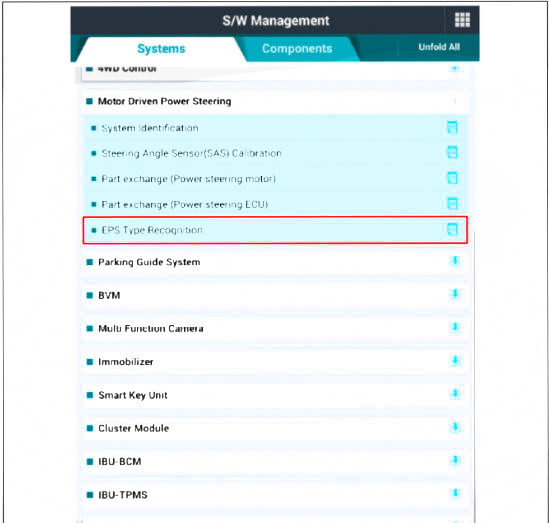
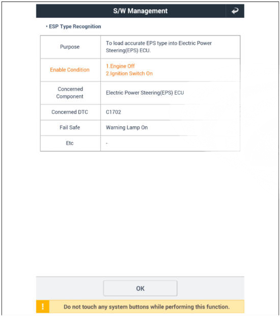

- Remove the DTC.
- Turn off the IG switch and wait for 20 seconds or more before starting the engine. And then make sure that MDPS works properly.
SAS Calibration
- Steering-angle sensor detects the steering angle and steering angle speed. Steering angle and steering angle speed are used for steering wheel damping and return controls in addition to providing assistance torque.
WARNING
- You can use a scan tool to (diagnostic tool) check if the battery voltage is proper before perform the "SAS Calibration".
- Make sure that no connector engaged to the vehicle or scan tool is disconnected during the "SAS Calibration".
- Once the "SAS Calibration" is complete, turn off the IG switch and wait for 10 seconds or more before starting the engine to check the operation.
SAS Calibration procedures
- Connect self - diagnosis connector (16pins) located in the lower of driver side crash pad to self - diagnosis device.
- Turn the self - diagnosis device after key is ON.
- Turn the steering wheel to straight ahead position.
- After Selecting the "vehicle model" and "system", select the "SAS Calibration" on diagnostic tool vehicle selection screen.


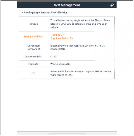
- Remove the DTC.
- Turn off the IG switch and wait for 10 seconds or more before starting the engine. And then make sure that MDPS works properly.
Replacement
C-MDPS
- Turn the steering wheel so that the front wheels are placed in the straight ahead position.
- Turn the ignition switch OFF and disconnect the battery negative (-) cable.
- Remove the driver airbag (DAB).
(Refer to Restraint - "Driver Airbag (DAB) Module and Clock Spring")
- Remove the steering wheel.
(Refer to Steering System - "Steering wheel")
- Remove the clock spring.
(Refer to Restraint - "Driver Airbag (DAB) Module and Clock Spring")
- Remove the multifunction switch.
(Refer to Body Electrical System - "Multifunction switch")
- Remove the steering column shroud lower panel.
(Refer to Body - "Steering Column Shroud lower Panel")
- Remove the crash pad lower pannel.
(Refer to Body - "Crash Pad Lower Pannel")
- Remove the brake pedal.
(Refer to Brake System - "Brake Pedal")
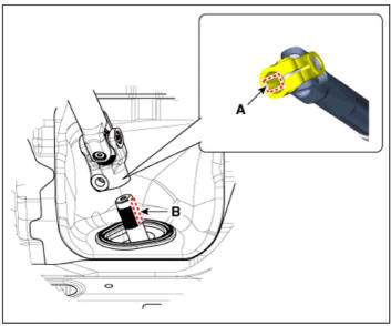
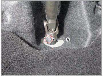
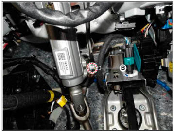
- Disconnect the MDPS connector (A. B).
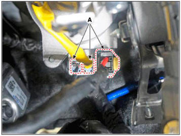
- Separate the universal joint from the steering gear box after loosening the universal joint mounting bolt (A).
Tightening torque : 53.9 - 58.8 N.m (5.5 - 6.0 kgf.m. 39.8 - 43.4 lb-ft)
WARNING
- Lock the steering wheel in the straight ahead position to prevent the damage of the clock spring inner cable.
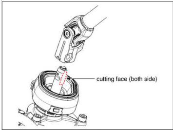
- When mounting, securely insert the universal joint into the steering gear box pinion shaft.
- Do not reuse the universal joint bolt.
- Assemble so that pinion shaft shark pin can be inserted between the joint slots.
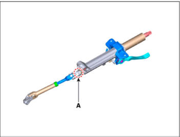
- Install by aligning the machining surface (A) of the universal
joint and the machining surface (B) of the steering
gearbox pinion shaft.
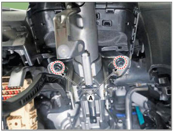
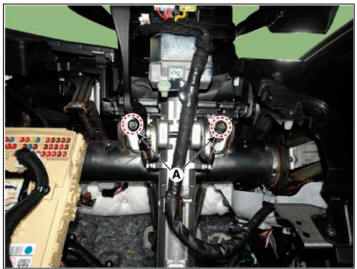
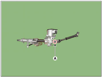
- Remove the steering column assembly after loosening the mounting nuts (A) and bolt (B).
Tightening torque :
(A): 25.0 - 29.4 N.m (2.5 - 3.0 kgf.m, 14.5 - 21.7 lb-ft)
(B): 53.9 - 58.8 N.m (5.5 - 6.0 kgf.m. 39.8 - 43.4 lb-ft)
- To install, reverse the removal procedures.
WARNING
When installing a new power pack, be sure to check whether the coupling is assembled before installing it.
- Set the Steering angle zero point by using the diagnostic tool.
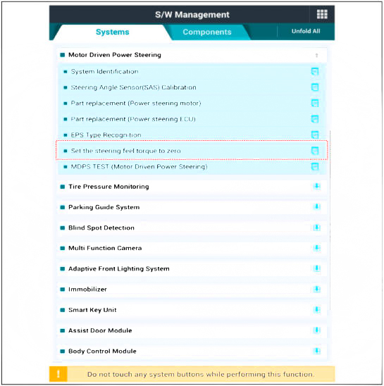
- Conduct the "EPS Type Recognition" by diagnostic tool.
(Refer to MDPS PowerPack Assembly - "Diagnosis with diagnostic tool")
- Conduct the "ASP Calibration" by diagnostic tool.
(Refer to MDPS PowerPack Assembly - "Diagnosis with diagnostic tool")
- Conduct the MDPS Performance Inspection using the diagnostic tool.
(Refer to Motor Driven Power Steering - "Repair procedures")
- Check the DTC.
- Turn off the IGN switch and wait for 20 seconds or more. Then check the operation after starting the engine.
R-MDPS
- Turn the steering wheel so that the front wheels are placed in the straight ahead position.
- Turn the ignition switch OFF and disconnect the battery negative (-) cable.
- Remove the driver airbag (DAB).
(Refer to Restraint - "Driver Airbag (DAB) Module and Clock Spring")
- Remove the steering wheel.
(Refer to Steering System - "Steering wheel")
- Remove the clock spring.
(Refer to Restraint - "Driver Airbag (DAB) Module and Clock Spring")
- Remove the multifunction switch.
(Refer to Body Electrical System - "Multifunction switch")
- Remove the steering column shroud lower panel.
(Refer to Body - "Steering Column Shroud lower Panel")
- Remove the crash pad lower pannel.
(Refer to Body - "Crash Pad Lower Pannel")
- Remove the brake pedal.
(Refer to Brake System - "Brake Pedal")
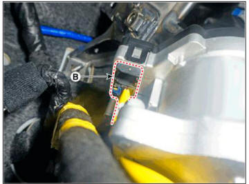
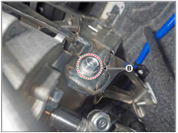
- Disconnect the electric steering column lock switch connector (A).
- Remove the fixing clip (B) from the steering column.

- Separate the universal joint from the steering gear box after loosening the universal joint mounting bolt (A)
Tightening torque : 53.9 - 58.8 N.m (5.5 - 6.0 kgf.m. 39.8 - 43.4 lb-ft)
WARNING
- Do not reuse the bolt.
- Lock the steering wheel in the straight ahead position to prevent the damage of the clock spring inner cable.
- Assemble so that the universal joint hole is inserted matching
the cut surface of the pinion shaft.
- Remove the MDPS assembly by loosening the mounting nuts (A) and bolt (B).
Tightening torque
(A): 25.0 - 29.4 N.m (2.5 - 3.0 kgf.m, 14.5 - 21.7 lb-ft)
(B): 53.9 - 58.8 N.m (5.5 - 6.0 kgf.m. 39.8 - 43.4 lb-ft)
- To install, reverse the removal procedures.
Disassembly
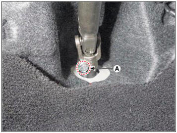
- Loosen the bolt (A) and then disconnect the universal joint assembly from the steering column assembly.
Tightening torque : 49.0 - 58.8 N.m (5.0 - 6.0 kgf.m, 39.8 - 43.4 lb-ft)
C-MDPS
R-MDPS
WARNING
Do not reuse the universal joint bolt.
- Reassembly is the reverse of the disassembly.
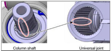
WARNING
When assembling, match the gear teeth as the below illustration.
READ NEXT:
 Motor Driven Power Steering - Removal and installation
WARNING
When lifting a vehicle using a lift, be careful not to damage the
lower parts of the vehicle (floor under cover, fuel filter, fuel
tank, canister).
(Refer to General Information - "Lift Point")
Loosen the front wheel nuts
Tie rod end
Remove the tie rod end after loosening the nut.
Tightening torque :
49.0 - 53.9 N.m (5.0 - 5.5 kgf.m, 36.2 - 39.8 lb-ft)
WARNING
Before removing the tie rod end, note by measuring the length of the
thread or marked with paint.
Repl
SEE MORE:
Interior lights
WARNING
Do not use the interior lights when
driving in the dark. The interior lights
may obscure your view and cause an
accident.
NOTICE
Do not use the interior lights for
extended periods when the vehicle is
turned off or the battery will di
Forward Collision-Avoidance Assist Settings
Setting features
Forward Safety
With the engine on, select 'Driver
Assistance → Forward Safety' from the
Settings menu to set whether or not to
use each function.
If 'Active Assist' is selected, Forward
Collision-Avoidance Assis
Information
- Home
- Hyundai Tucson - Fourth generation (NX4) - (2020-2023) - Owner's Manual
- Hyundai Tucson - Fourth generation (NX4) - (2020-2023) - Workshop Manual
