Hyundai Tucson: Motor Driven Power Steering - Removal and installation
WARNING
When lifting a vehicle using a lift, be careful not to damage the lower parts of the vehicle (floor under cover, fuel filter, fuel tank, canister).
(Refer to General Information - "Lift Point")
- Loosen the front wheel nuts slightly.
Raise the vehicle, and make sure it is securely supported.
- Remove the front wheel and tire.
(Refer to Suspension System - "Wheel")
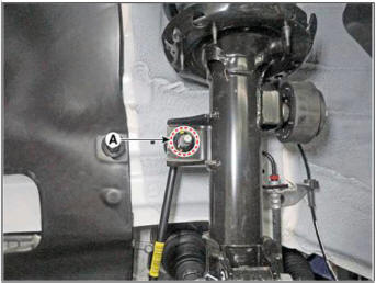
- Disconnect the stabilizer link with the front strut assembly after loosening the nut (A).
Tightening torque : 98.1 - 117.7 N.m (10.0- 12.0 kgf.m, 72.3 - 86.8 lb-ft)
WARNING
- When loosening the nut, fix the outer hexagon of stabilizer bar link.
- Be careful not to damage the stabilizer link boots.
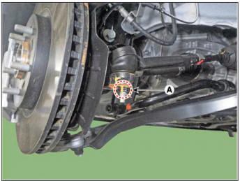
- Remove the split pin and tie rod end ball joint nut (A).
Tightening torque: 98.1 - 117.7 N.m (10.0- 12.0 kgf.m, 72.3 - 86.8 lb-ft)
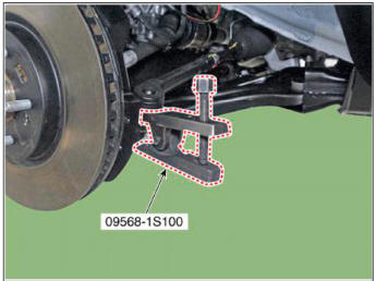
- Remove the tie rod end ball joint (A) using the SST (09568-1S100).
- Loosen the front lower arm bolt and nut (A).
Tightening torque: 98.0- 117.6 N.m (10.0- 12.0 kgf.m, 72.3 - 86.7 lb-ft)

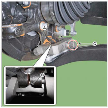
- Remove the lower arm from the knuckle by using the SST (09568-4R100).
(1) Install the support bolt (A) from lower arm bolt hole.
(2) Install the support body (B) from front axle.
(3) Tighten the bolt (C).
- Separate the universal joint from the steering gear box after loosening the universal joint mounting bolt (A).
Tightening torque : 53.9 - 58.8 N.m (5.5 - 6.0 kgf.m, 39.8 - 43.4 lb-ft)
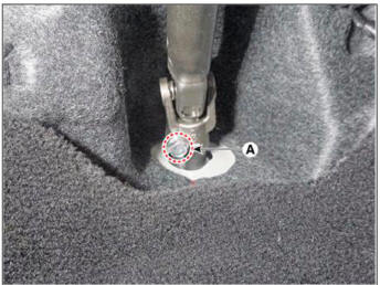
WARNING
- Do not reuse the bolt.
- Lock the steering wheel in the straight ahead position to prevent the damage of the clock spring inner cable.
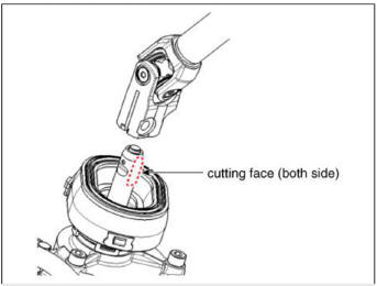
- Assemble so that the universal joint hole is inserted matching
the cut surface of the pinion shaft.
- Remove the under cover.
(Refer to Engine Mechanical System - "Engine Room Under Cover")
- Disconnect the R-MDPS main connector (A). R-MDPS Type only
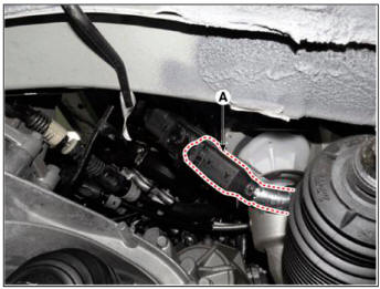
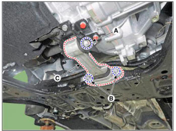
- Remove the muffler rubber hanger (A) from the sub frame after loosening the mounting nut.
Tightening torque : 19.6 - 25.5 N.m (2.0 - 2.6 kgf.m, 14.5 - 18.8 lb-ft)
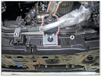
- Remove the roll rod bracket (C) after loosening the bolt (A), (B).
Tightening torque :
(A): 107.9 - 127.5 N.m (11.0- 13.0 kgf.m, 79.6-94.0 lb-ft)
(B): 49.0 - 63.7 N.m (5.0 - 6.5 kgf.m, 36.2 - 47.0 lb-ft)
WARNING
Set a transmission jack tor safety.
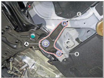
- Remove the sub frame stay after loosening the mounting bolts (A, B) and nut (C).
Tightening torque :
(A): 176.5 - 196.1 N.m (18.0-20.0 kgf.m, 130.2 - 144.7 b-ft)
(B): 44.1 - 53.9 N.m (4.5 - 5.5 kgf.m, 32.5 - 39.8 lb-ft)
(C): 44.1 - 53.9 N.m (4.5 - 5.5 kgf.m, 32.5 - 39.8 lb-ft)
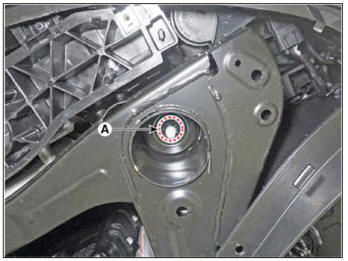
- Loosen the sub frame mounting nuts (A).
Tightening torque : 176.5 - 196.1 N.m (18.0 - 20.0 kgf.m, 130.2 - 144.7 b-ft)
- Remove the sub frame.
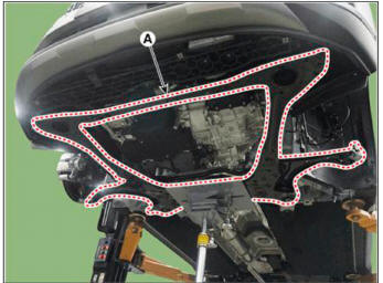
- Remove the heat protector (A).
Tightening torque : 7.8 - 11.8 N.m (0.8 - 1.2 kgf.m, 5.8 - 8.7 lb-ft)
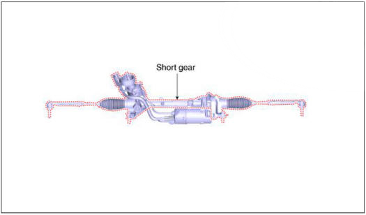
C-MDPS
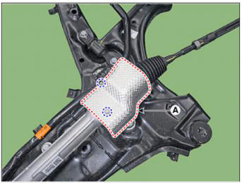
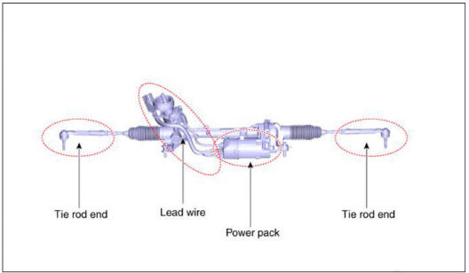
R-MDPS
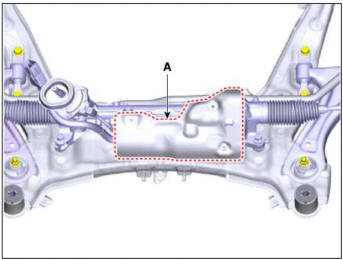
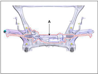
- Remove the steering gearbox (A) from the front sub frame after loosening the mounting bolts.
Tightening torque : 107.9 - 127.5 N.m (11.0 - 13.0 kgf.m, 79.6 - 94.0 lb-ft)
C-MDPS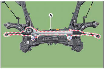
R-MDPS
- To install, reverse the removal procedures.
- Check the alignment.
(Refer to Suspension System - "Alingment")
- Conduct the "EPS Type Recognition" by diagnostic tool.
(Refer to Motor Driven Power Steering - "Diagnosis with diagnostic tool")
Replacement
WARNING
- Do not disassembly the steering gear box.
- If disassembly the steering gear box. the quality(Noise / cleanliness / functions) is not guaranteed.
C-MDPS
R-MDPS
READ NEXT:
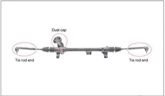
 Tie rod end
Remove the tie rod end after loosening the nut.
Tightening torque :
49.0 - 53.9 N.m (5.0 - 5.5 kgf.m, 36.2 - 39.8 lb-ft)
WARNING
Before removing the tie rod end, note by measuring the length of the
thread or marked with paint.
Repl
General Information
Please read the following precautions carefully before performing the airbag
system service.
Observe the instructions described in this manual, or the airbags could
accidentally deploy and cause
damage or injuries.
Except when performing
SEE MORE:
Engine Overheat/
Troubleshooting
Components
Water pipe
Water hose
Integrated thermal management module (ITM)
Heater pipe
Turbo charger coolant hose
Heater hose
Heater pipe A
Heater pipe A gasket
Oil cooler hose A
Oil cooler pipe
Oil cooler hose B
Water
Concentric Slave Cylinder Assembly - Removal
Gasoline 1.6 T-GDI / Gasoline 2.0 MPI
Remove the manual transaxle assembly.
(Refer to In case by Gasoline 1.6 T-GDI System - "Manual Transaxle")
(Refer to In case by Gasoline 1.6 T-GDI System - "Intelligent Manual
Transaxle&q
Information
- Home
- Hyundai Tucson - Fourth generation (NX4) - (2020-2023) - Owner's Manual
- Hyundai Tucson - Fourth generation (NX4) - (2020-2023) - Workshop Manual
