Hyundai Tucson: Engine Control - Fuel System - Description and Operation
Description
If the Gasoline Engine Control system components (sensors, ECM, injector, etc.) fail, interruption to the fuel supply or failure to supply the proper amount of fuel for various engine operating conditions will result. The following situations may be encountered.
- Engine is hard to start or does not start at all.
- Unstable idle.
- Poor driveability
If any of the above conditions are noted, first perform a routine diagnosis that includes basic engine checks (ignition system malfunction, incorrect engine adjustment, etc.). Then, inspect the Gasoline Engine Control system components with the HISCAN (Pro).
WARNING
- Before removing or installing any part, read the diagnostic trouble codes and then disconnect the battery negative (-) terminal.
- Before disconnecting the cable from battery terminal, turn the ignition switch to OFF. Removal or connection of the battery cable during engine operation or while the ignition switch is ON could cause damage to the ECM.
- The control harnesses between the ECM and heated oxygen sensor are shielded with the shielded ground wires to the body in order to prevent the influence of ignition noises and radio interference. When the shielded wire is faulty, the control harness must be replaced.
- When checking the generator for the charging state, do not disconnect the battery '+' terminal to prevent the ECM from damage due to the voltage.
- When charging the battery with the external charger, disconnect the vehicle side battery terminals to prevent damage to the ECM.
Malfunction Indicator Lamp (MIL)
EOBD
A malfunction indicator lamp illuminates to notify the driver that there is a problem with the vehicle. However, the MIL will go off automatically after 3 subsequent sequential driving cycles without the same malfunction. Immediately after the ignition switch is turned on (ON position - do not start), the MIL will illuminate continuously to indicate that the MIL operates normally.
Faults with the following items will illuminate the MIL.
- Catalyst
- Fuel system
- Manifold Absolute Pressure Sensor (MAPS)
- Intake Air Temperature Sensor (IATS)
- Engine Coolant Temperature Sensor (ECTS)
- Throttle Position Sensor (TPS) integrated into ETC Module
- Upstream Oxygen Sensor
- Upstream Oxygen Sensor Heater
- Downstream Oxygen Sensor
- Downstream Oxygen Sensor Heater
- Injector
- Misfire
- Crankshaft Position Sensor (CKPS)
- Camshaft Position Sensor (CMPS)
- Evaporative Emission Control System
- Vehicle Speed Sensor (VSS)
- ETC Motor integrated into ETC Module
- Power Supply
- ECM/ PCM
- MT/AT Encoding
- Acceleration Sensor
- MIL-on Request Signal
- Power Stage
WARNING
Refer to "Inspection CHART FOR DIAGNOSTIC TROUBLE CODES (DTC)" for more information.
NON-EOBD
A malfunction indicator lamp illuminates to notify the driver that there is a problem with the vehicle. However, the MIL will go off automatically after 3 subsequent sequential driving cycles without the same malfunction. Immediately after the ignition switch is turned on (ON position - do not start), the MIL will illuminate continuously to indicate that the MIL operates normally.
Faults with the following items will illuminate the MIL
- Heated oxygen sensor (HO2S)
- Manifold Absolute Pressure Sensor (MAPS)
- Throttle Position Sensor (TPS) integrated into ETC Module
- Engine coolant temperature sensor (ECTS)
- ETC Motor integrated into ETC Module
- Injectors
- ECM
WARNING
Refer to "Inspection CHART FOR DIAGNOSTIC TROUBLE CODES (DTC)" for more informayion
Inspection
- After turning ON the ignition key, ensure that the light illuminates for about 5 seconds and then goes out.
- If the light does not illuminate, check for an open circuit in the harness, a blown fuse or a blown bulb.
Self-Diagnosis
The ECM monitors the input/output signals (some signals at all times and the others under specified conditions). When the ECM detects an irregularity, it records the diagnostic trouble code, and outputs the signal to the Data Link connector. The diagnosis results can be read with the MIL or HI-SCAN (Pro). Diagnostic Trouble Codes (DTC) will remain in the ECM as long as battery power is maintained. The diagnostic trouble codes will, however, be erased when the battery terminal or ECM connector is disconnected, or by the HI-SCAN (Pro).
WARNING
If a sensor connector is disconnected with the ignition switch turned on, the diagnostic trouble code (DTC) is recorded. In this case, disconnect the battery negative terminal (-) for 15 seconds or more, and the diagnosis memory will be erased.
The Relation Between DTC and Driving Pattern In EOBD System
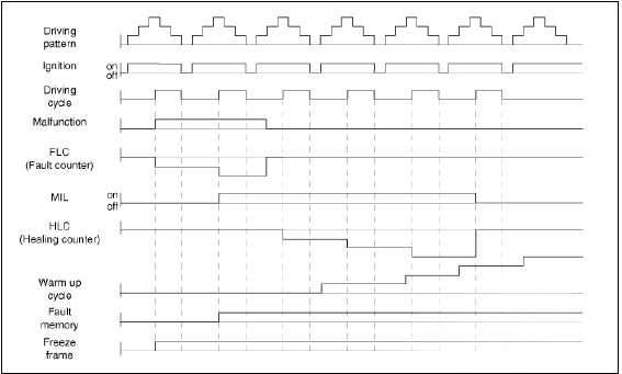
- When the same malfunction is detected and maintained during two sequential driving cycles, the MIL will automatically illuminate.
- The MIL will go off automatically if no fault is detected after 3 sequential driving cycles.
- A Diagnostic Trouble Code (DTC) is recorded in ECM memory when a
malfunction is detected after two sequential
driving cycles. The MIL will illuminate when the malfunction is detected on
the second driving cycle.
If a misfire is detected, a DTC will be recorded, and the MIL will illuminate, immediately after a fault is first detected.
- A Diagnostic Trouble Code (DTC) will automatically erase from ECM memory if the same malfunction is not detected for 40 driving cycles
WARNING
- A "warm-up cycle" means sufficient vehicle operation such that the coolant temperature has risen by at least 40 degrees Fahrenheit from engine starting and reaches a minimum temperature of 160 degress Fahrenheit.
- A "driving cycle" consists of engine startup, vehicle operation beyond the beginning of closed loop operation.
READ NEXT:
 Components and Components Location
Components Location
Engine Control Module (ECM)
Mass Air Flow Sensor (MAFS)
Manifold Absolute Pressure Sensor (MAPS)
Intake Air Temperature Sensor (IATS)
Boost Pressure Sensor (BPS)
Engine Coolant Temperature Sensor (E
Engine Control Module (ECM)
ECM Terminal And Input/Output signal
ECM Terminal Function
Connector A
Connector B
Engine Control Module (ECM) - Removal
Removal
Turn ignition switch OFF and disconnect the battery negative (-)
terminal
Mass Air Flow Sensor (MAFS)
Description
MAFS uses a hot-film type sensing element to measure the mass of intake air
entering the engine, and
send the signal to ECM.
A large amount of intake air represents acceleration or high load conditions
while a small amount of
in
SEE MORE:
Auto Head Lamp Leveling Device
Component Location
Head lamp leveling actuator (Inside head lamps)
Head lamp leveling switch
Removal
Disconnect the negative (-) battery terminal.
Remove the crash pad lower panel.
(Refer to Body - "Crash Pad Lower Panel&q
Cylinder Block/ Disassembly/ Inspection/ Reassembly
WARNING
Use fender covers to avoid damaging painted surfaces.
To avoid damage, unplug the wiring connectors carefully while
holding the connector portion.
WARNING
Mark all wiring connector and hoses to avoid misconnection.
To releas
Information
- Home
- Hyundai Tucson - Fourth generation (NX4) - (2020-2023) - Owner's Manual
- Hyundai Tucson - Fourth generation (NX4) - (2020-2023) - Workshop Manual
