Hyundai Tucson: Engine Control Module (ECM)
ECM Terminal And Input/Output signal
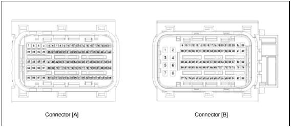
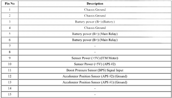
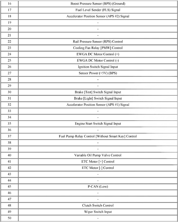
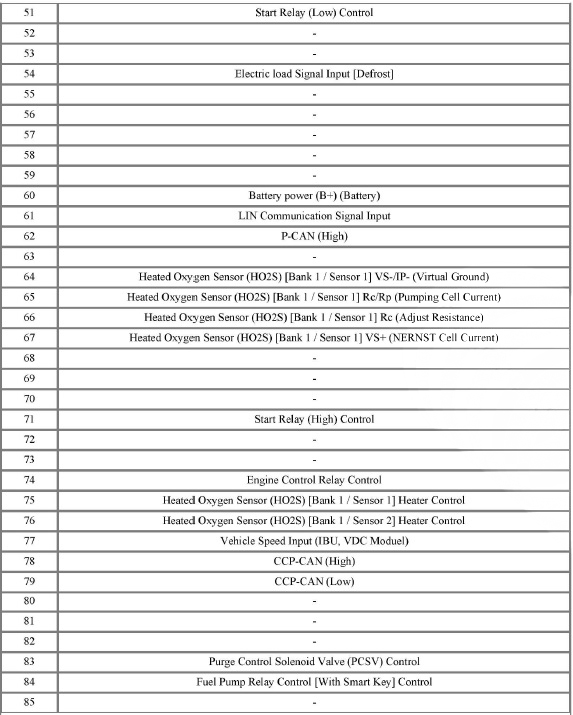
ECM Terminal Function
Connector A
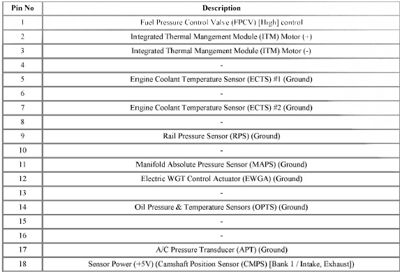
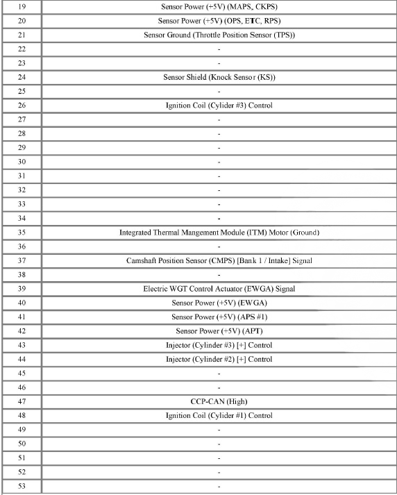
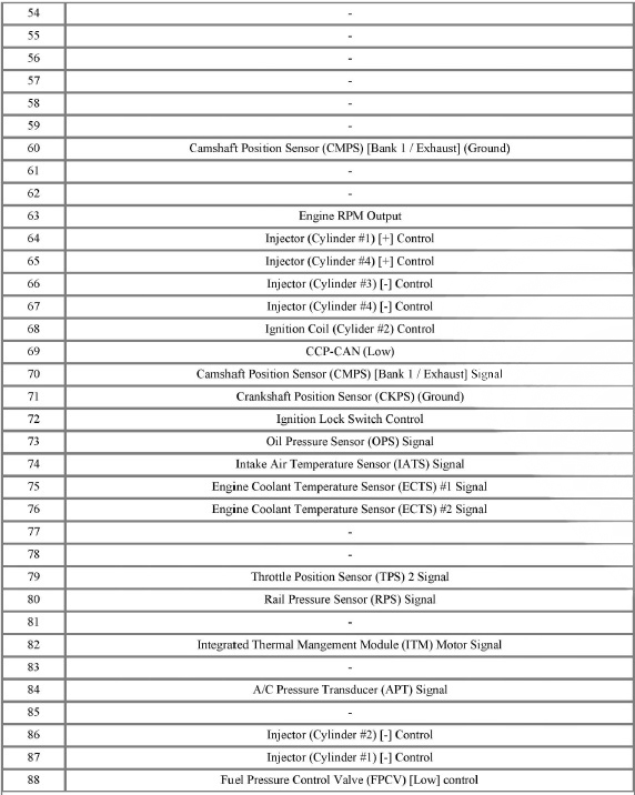
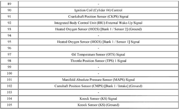
Connector B
Engine Control Module (ECM) - Removal
Removal
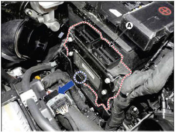
- Turn ignition switch OFF and disconnect the battery negative (-) terminal.
- Disconnect the ECM Connector (A).

- Remove the air cleaner assembly.
(Refer to Engine Mechanical - "Air Cleaner")
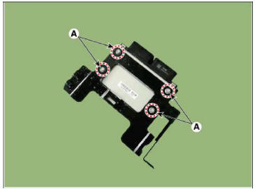
- Remove the ECM (A) after releasing the fixing hooks.
- Remove the ECM (B) after loosening the mounting bolts (A).
Tightening Torque : 9.8 - 11.8 N.m (1.0 - 1.2 kgf.m, 7.2 - 8.7 lb-ft)
Engine Control Module (ECM)- Installation
Installation
- Install in the reverse order of removal.
Inspection
- TEST ECM GROUND CIRCUIT : Measure resistance between ECM and chassis ground using the backside of ECM harness connector as ECM side check point. If the problem is found, repair it.
Specification : Below 1

- TEST ECM CONNECTOR : Disconnect the ECM connector and visually check the ground terminals on ECM side and harness side for bent pins or poor contact pressure. If the problem is found, repair it.
- If problem is not found in Step 1 and 2, the ECM could be faulty. If so, make sure there were no DTC's before swapping the ECM with a new one, and then check the vehicle again. If DTC's were found, examine this first before swapping ECM.
- RE-TEST THE ORIGINAL ECM : Install the original ECM (may be broken) into a known-good vehicle and check the vehicle. If the problem occurs again, replace the original ECM with a new one. If problem does not occur, this is intermittent problem.
(Refer to "Intermittent Problem Inspection Procedure" in Basic Inspection Procedure)
Adjustment
ECM neutralization procedure (With immobilizer)
- When replacing the ECM, the vehicle equipped with the immobilizer must be performed procedure as below.
In the case of installing used ECM
1)Perform "ECM Neutral mode" procedure with diagnostic tool.
(Refer to Body Electrical System - "Immobilizer System")
2)After finishing "ECM Neutral mode", perform "Keyteaching" procedure with diagnostic tool.
(Refer to Body Electrical System - "Immobilizer System")
In the case of installing new ECM
- Perform "Key teaching" procedure with diagnostic tool.
(Refer to Body Electrical System - "Immobilizer System")
ECM Neutralization procedure (With smart key)
WARNING
When replacing the ECM, the vehicle equipped with the smart key system (Button start) must be performed procedure as below.
In the case of installing used ECM
1)Perform "ECM Neutral mode" procedure with diagnostic tool.
(Refer to Body Electrical System - "Smart Key Diagnostic")
2)After finishing "ECM Neutral mode", insert the key (or press the start button) and turn it to the IGN ON and OFF position. Then the ECM learns the smart key information automatically.
In the case of installing new ECM
- Insert the key (or press the start button) and turn it to the IGN ON and OFF position. Then the ECM learns the smart key information automatically.
ETC Module Learning Process
After replacing or re-installing the ECM, if you do not perform the ETC module learning procedure, the ETC module learning procedure must be performed since shift shock or failure code may be displayed.
(Refer to Engine Control System - "ETC System")
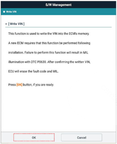
VIN Programming Procedure
VIN (Vehicle Identification Number) is a number that has the vehicle's information (Maker, Vehicle Type, Vehicle Line/Series.
Body Type, Engine Type, Transmission Type, Model Year, Plant Location and so forth. For more information, please refer to the group "GI" in this SERVICE MANUAL). When replacing an ECM, the VIN must be programmed in the ECM. If there is no VIN in ECM memory, the fault code (DTC P0630) is set.
WARNING
The programmed VIN cannot be changed. When writing the VIN, confirm the VIN carefully.
- Turn the ignition switch OFF.
- Connect the diagnostic tool to Data Link Connector (DLC).
- Turn the igntion switch ON.
- Select "Vehicle, Model Year, Engine, System".
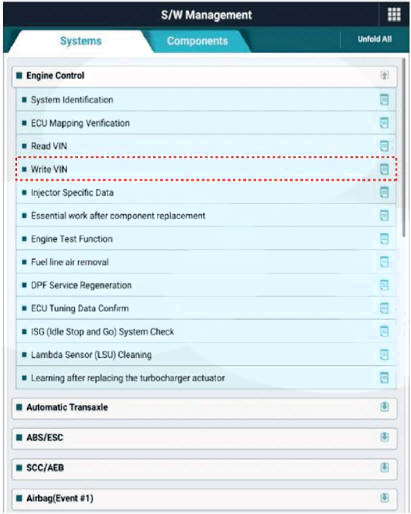
- Select "Vehicle S/W Management".
- Select "Write VIN".
READ NEXT:
 Mass Air Flow Sensor (MAFS)
Description
MAFS uses a hot-film type sensing element to measure the mass of intake air
entering the engine, and
send the signal to ECM.
A large amount of intake air represents acceleration or high load conditions
while a small amount of
in
Boost Pressure Sensor (BPS)
Description
Boost pressure sensor (BPS) is installed on top of intercooler output pipe to
measures the pressure of
supercharged air in the turbocharger.
Specification
Circuit Diagram
Harness Connector
Inspection
Connect th
ETC (Electronic Throttle control) System
Description
The Electronic Throttle Control (ETC) System consists of a throttle body with
an integrated control motor and throttle
position sensor (TPS). Instead of the traditional throttle cable, an Accelerator
Position Sensor (APS) is used to
SEE MORE:
IMT System Actuator- Installation
Installation
Install the IMT system actuator (A) and then tightening the bolts.
Tightening torque:
19.6 - 26.5 N.m (2.0 - 2.7 kgf.m. 14.5 - 19.5 lb-ft)
Lightly install the concentric slave cylinder (B) on the input shaft
(A).
Front Axle Assembly
Components
Front brake disc
Front hub assembly
Dust cover
Front knuckle
Removal
WARNING
When lifting a vehicle using a lift, be careful not to damage
the lower parts of the vehicle (floor under cover,
fuel filter, fuel tank
Information
- Home
- Hyundai Tucson - Fourth generation (NX4) - (2020-2023) - Owner's Manual
- Hyundai Tucson - Fourth generation (NX4) - (2020-2023) - Workshop Manual
