Hyundai Tucson: ETC (Electronic Throttle control) System
Description
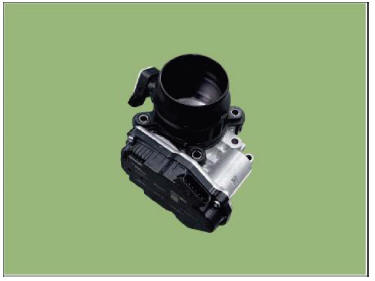
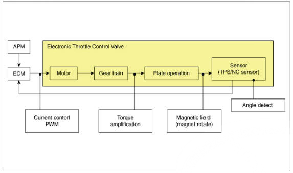
The Electronic Throttle Control (ETC) System consists of a throttle body with an integrated control motor and throttle position sensor (TPS). Instead of the traditional throttle cable, an Accelerator Position Sensor (APS) is used to receive driver input. The ECM uses the APS signal to calculate the target throttle angle; the position of the throttle is then adjusted via ECM control of the ETC motor. The TPS signal is used to provide feedback regarding throttle position to the ECM. Using ETC, precise control over throttle position is possible; the need for external cruise control modules/cables is eliminated.
Fail-safe Mode

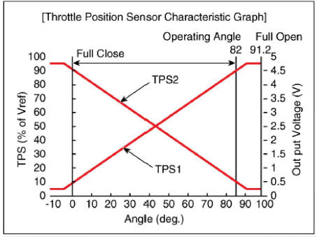
- When throttle value is stuck at 9.2º, engine speed is limited at below 1,200 - 1700 rpm.
Specification
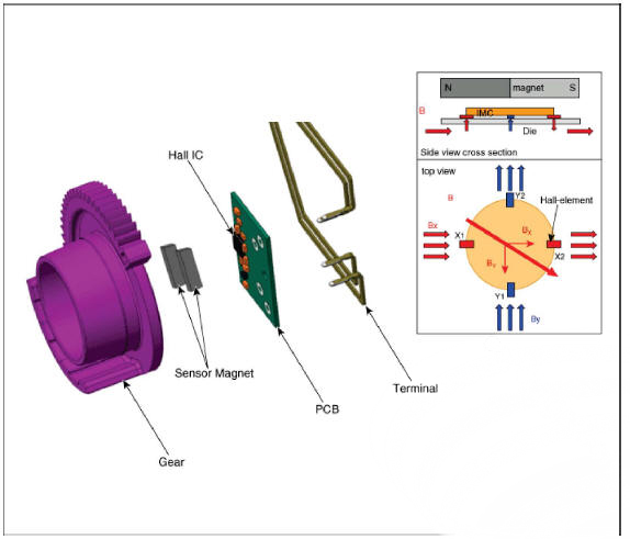
 Throttle Position Sensor (TPS)
 Type
: IC Rotation Sensor type
Type
: IC Rotation Sensor type
Specification
ETC Motor

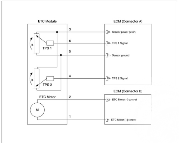
Schematic Diagram
Circuit Diagram
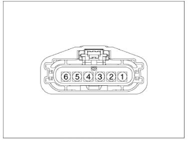
Harness Connector
Inspection
Throttle Position Sensor (TPS)
- Connect a diagnostic tool on the Data Link Connector (DLC).
- Start engine and check output voltages of TPS 1 and 2 at C.T and W.O.T.
Specification : Refer to Specification Section.
ETC Motor
- Turn the ignition switch OFF.
- Disconnect the ETC module connector.
- Measure resistance between the ETC module terminals 1 and 2.
- Check that the resistance is within the specification.
Specification : Refer to Specification Section
Removal
- Turn ignition switch OFF and disconnect the battery negative (-) terminal.
- Remove the Intercooler outlet hose.
(Refer to Engine Mechanical - "Intercooler")
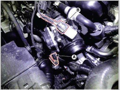
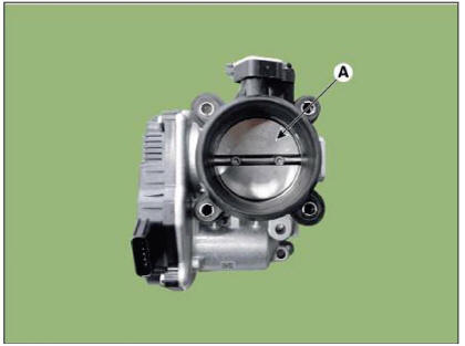
- Disconnect the ETC module connector (A).
- Disconnect BPS connector (B).
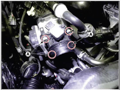
- Remove the ETC module after remove the mounting bolt (A).
Tightening Torque : 9.8 - 11.8 N.m (1.0 - 1.2 kgf.m, 7.2 - 8.7 lb-ft)
Cleaning
- Remove the ETC Module.
(Refer to Engine Control System - "ETC System")
- Keep the ETC module plate (A) open.
- Clean the pollutant in the throttle body with a soft cloth moistened with cleaning fluid
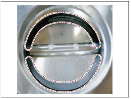
- Do not spray cleaning fluid directly onto ETC. Use a lint free cloth moistened with cleaning fluid.
- Be careful not to clean the coating fluid around the shaft. If coating fluid is removed, idling control failure might occur by foreign substance inflow or excessive air leakage.
- After cleaning, re-install the ETC module and then perform the ETC module learning procedure.
(Refer to Engine Control System - "ETC System")
Installation
WARNING
- Install the component to the specified torques.
- Note that internal damage may occur when the component is dropped. In this case, use it after inspecting.
- Install in the reverse order of removal.
Adjustment
ETC Module Learning Procedure
Be sure to perform the ETC module learning procedure when replacing or re-installing the ETC module.
- Wait for 1 minute with the ignition switch ON.
- Start the engine and hold the idle status for 15 minutes.
- Waif for 1 minute with the ignition switch OFF.
- Restart the engine, and check that the idle speed is stable.
WARNING
If the ETC module learning procedure is not performed after replacing or reinstalling the ETC module, MIL illumination with DTCs may occur.
READ NEXT:
 Manifold Absolute Pressure Sensor (MAPS)
Description
Manifold Absolute Pressure Sensor (MAPS) is a speed-density type sensor and
is installed on the
surge tank. It senses absolute pressure of the surge tank and transfers the
analog signal proportional to
the pressure to the ECM. By u
Intake Air Temperature Sensor (IATS)
Description
Intake Air Temperature Sensor (IATS) is included inside Manifold Absolute
Pressure Sensor and
detects the intake air temperature.
To calculate precise air quantity, correction of the air temperature is needed
because air density
Engine Coolant Temperature Sensor (ECTS)
Description
The Engine Coolant Temperature Sensor (ECTS) is located in the cylinder block
and cylinder head,
and measures the temperature of the engine coolant. The thermistor of the
cooling water temperature
and resistance has a negative temp
SEE MORE:
Connector Inspection Procedure
Handling of Connector
a.Never pull on the wiring harness when disconnecting connectors.
b.When removing the connector with a lock, press or pull locking lever.
c.Listen for a click when locking connectors. This sound indicates that th
Engine Oil - Removal and Installation
Disconnect the battery negative terminal.
Remove the engine room under cover.
(Refer to Engine and Transaxle Assembly - "Engine Room Under Cover")
Drain the coolant.
(Refer to Cooling System - "Coolant")
D
Information
- Home
- Hyundai Tucson - Fourth generation (NX4) - (2020-2023) - Owner's Manual
- Hyundai Tucson - Fourth generation (NX4) - (2020-2023) - Workshop Manual
