Hyundai Tucson: ECS (Electronic Control Suspension) System
Description
Real-time continuous control of the damping force according to vehicle running conditions and the state of road surface will enhance ride comfort and steering safety, including roll / pitch reduction in case of vehicle dynamics control, quick turning, braking, and starting.
Operation
System
When power is supplied to ECU (IGN ON), ECU inspects the MCU and each part condition and then prepares operation. When engine starts operation (ENGINE ON), ECU operates the actuators.
System operation mode
Normal operation
It provides the "Comfort" and ""Sport" as 2 driver selective modes and the modes are changed linked with the integrated driving mode.
Emergency mode
If failure is detected, system is converted into the corresponding emergency mode according to the failure type and the warning light turns ON.
Damping control
The damping control can increase the ride quality and steering stability simultaneously. The damping control controls by classifying it into the sky hook control and adaptive control. The sky hook control performs the independent control by classifying the vehicle movement into the bounce, roll and pitch to improve the ride quality. The adaptive control ensures the driving stability at the specific driving conditions such as sudden lane change, sudden acceleration and sudden braking. The target current determined by each situation is achieved through the solenoid valve PWM 0~100% control.
The vertical velocity of vehicle body and damper is calculated using the vertical acceleration sensor signal of the vehicle body and wheels. The sky hook control determines the optimum damping force for 4 wheels using the speed of vehicle body and damper and controls the solenoid current of each wheel in real time,
- Deciding the road surface
For optimal control according to the each road condition, it controls by classifying the road conditions into 7 types Normal, rough road 1, rough road 2, wave, continuous wave, mound, port hole. The road condition is judged by the vertical acceleration sensor of the vehicle body. When more than 2 road conditions are judged simultaneously, it controls the road condition determined by priority that is set in advance. The road judgement can be corrected through the parameter calibration.
- Bounce controlling
The vertical velocity of vehicle body can be obtained by integrating the vehicle's vertical acceleration signal and the pitch velocity is calculated by the difference between the vehicle body speed of front and rear wheels. The required damping force is determined by multiplying the pitch velocity for each vehicle speed by proportional gain and the maximum damping force can be limited. The pitch proportional gain and the maximum damping force can be corrected by the calibration parameter and can control the independent value of front/rear wheels.
- Pitch control
The vertical velocity of vehicle body can be obtained by integrating the vehicle's vertical acceleration signal and the roll velocity is calculated by the difference between the vehicle body speed of left and right wheels. The required damping force is determined by multiplying the roll velocity for each vehicle speed by proportional gain and the maximum damping force can be limited. The roll proportional gain and the maximum damping force can be corrected by the calibration parameter and can control the independent value of front/rear wheels.
- Roll control
The vertical velocity of vehicle body can be obtained by integrating the vehicle's vertical acceleration signal and the roll velocity is calculated by the difference between the vehicle body speed of left and right wheels. The required damping force is determined by multiplying the roll velocity for each vehicle speed by proportional gain and the maximum damping force can be limited. The roll proportional gain and the maximum damping force can be corrected by the calibration parameter and can control the independent value of front/rear wheels.
- Damping speed estimation
The damper velocity can be estimated using the difference between the vertical velocity of wheels and vehicle body and the vertical velocity of wheels and vehicle body can be obtained by integrating the acceleration sensor signal. The rear wheel acceleration can be estimated through the vehicle's speed information and the front wheel acceleration sensor.
- Directivity check
The finally required damping force of sky hook is determined through the "Passivity Condition".
The "Passivity Check" determines the necessity of damping force control of damper. If the required damping force and the damper velocity are in the same direction, finally required damping force is set through the solenoid current control and if the direction is opposite, it is set as soft damping force.
Adaptive control
- Anti roll control
The sudden lane change situation is determined through the transverse jerk which is calculated by the steering angle sensor and vehicle speed signal. If the transverse jerk value exceeds the set value, steering stability can be increased by controlling the vehicle's roll movement with high damping force. The transverse jerk required to judge the sudden lane change can be set as the independent parameter for each vehicle speed and the target damping force can control the independent value of front/rear, left/right.
- Anti dive control
The sudden braking situation is determined through the brake M/C pressure sensor value. If the brake M/C pressure sensor value exceeds the set value, steering stability can be increased by controlling the vehicle's pitch movement with high damping force. The brake M/C pressure sensor value required to judge the sudden braking can be set as the independent parameter for each vehicle speed and the target damping force can control the independent value of front/rear.
- Anti squat control.
The sudden acceleration situation is determined through the acceleration pedal position value. If the acceleration pedal position value exceeds the set value, steering stability can be increased by controlling the pitch movement with high damping force. The acceleration pedal position value required to judge the sudden acceleration can be set as the independent parameter for each vehicle speed and the target damping force can control the independent value of front/rear.
- Vehicle speed sensing control
It determines the minimum damping force for each vehicle speed. Through this, it can achieve the comfortable ride at low speed and the stable driving performance at high speed. The target damping force can control the independent value of front/rear for each vehicle speed.
- Damping control mode
A driver can select one of the 2 driving modes (Comfort, Sport) by driver's preference and the damping mode is changed linked with the integrated driving mode.
- ECS Comfort: Integrated driving mode ECO&NORMAL train mode
- ECS Sport mode: Integrated driving mode Sport
When selecting driving mode, the calibration parameter stored in the ECU is changed according to the selected damping control mode and the vehicle movement performance is different according to the driving mode. Generally, Comport mode provides the optimal ride quality and steering stability and the Sport mode focuses on the steering stability.
Removal
- Turn ignition switch OFF and disconnect the negative (-) batteiy cable.
- Remove the luggage side trim.
(Refer to Body (Interior and Exterior) - "Luggage side trim")
- Disconnect the ECS control unit connector (A).
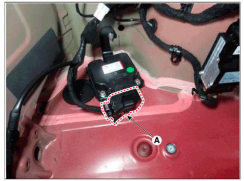
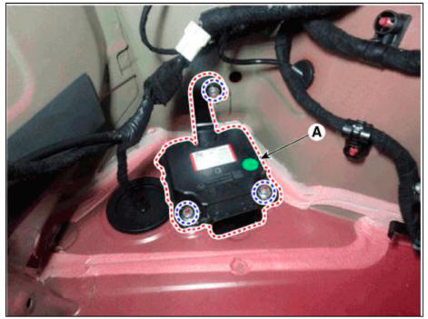
- Loosen the ECS control unit bracket nut and then remove the ECS control unit (A).
Tightening torque: 3.6 - 4.0 N.m (0.37 - 0.41 kgf.m, 2.7 - 3.0 lb-ft)
Installation
- To install, reverse the removal procedures.
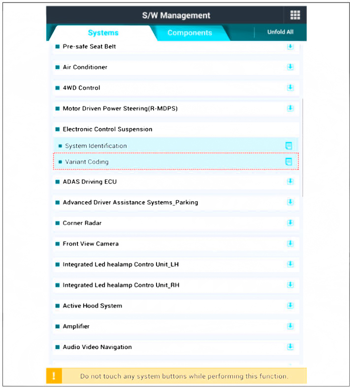
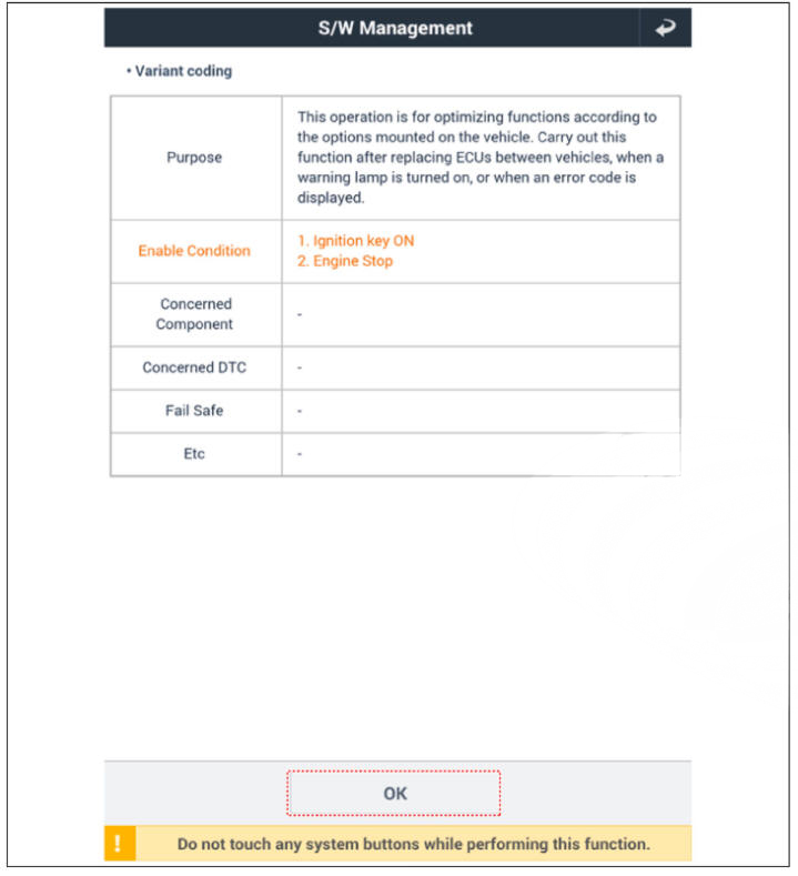
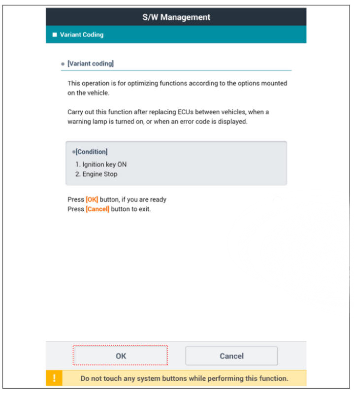
- Perform ECS variant coding.
READ NEXT:
 General Information
Troubleshooting
Specifications
Tightening torque
Special Service
Tools
Tool
(Number and
Name)/
Illustration/ Use
09568-1S100
Ball joint
remover/ / Removal of
the tie rod
end ball
joint.
09568-4R100
Lower arm
ball j
SEE MORE:
Display audio - Removal
Disconnect the negative (-) battery terminal.
Remove the front monitor lower cover (A).
Remove the front monitor lower cover after disconnecting the mood lamp
connector
Remove front monitor side cover (A) and (B).
Intelligent speed limit assist (ISLA)
Intelligent Speed Limit Assist uses
information from the detected road sign
and navigation system to inform the
driver of the speed limit and additional
information of the current road. Also,
Intelligent Speed Limit Assist helps the
driver to m
Information
- Home
- Hyundai Tucson - Fourth generation (NX4) - (2020-2023) - Owner's Manual
- Hyundai Tucson - Fourth generation (NX4) - (2020-2023) - Workshop Manual
