Hyundai Tucson: Crash pad side cover
Hyundai Tucson - Fourth generation (NX4) - (2020-2023) - Workshop Manual / Body (Interior and Exterior) / Crash Pad / Crash pad side cover
Component Location
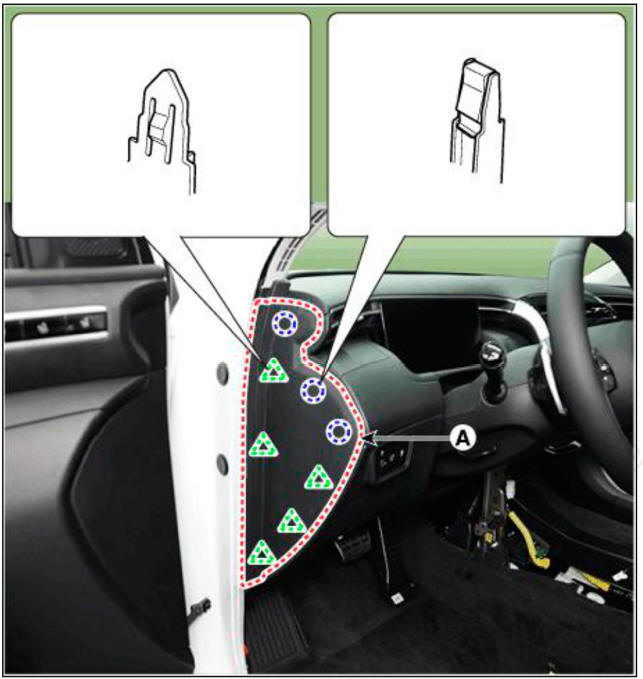
LH
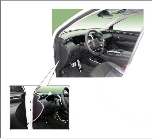
- Crash pad side cover LH
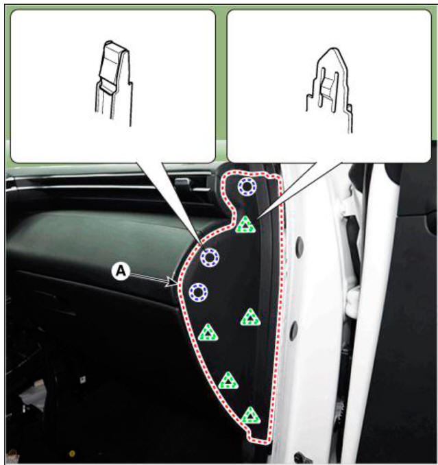
RH
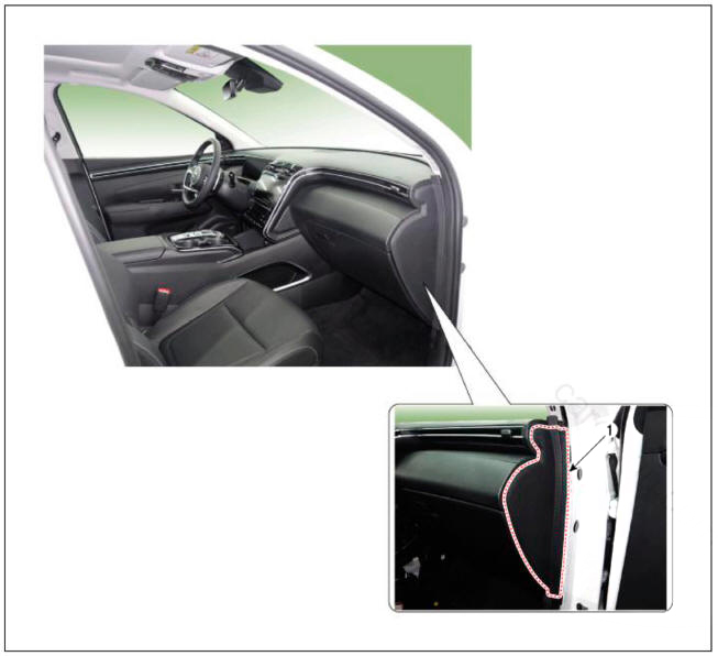
- Crash pad side cover RH
Replacement
WARNING
- When removing with a flat-tip screwdriver or remover, wrap protective tape around the tools to prevent damage to components.
- Put on gloves to prevent hand injuries.
WARNING
Take care not to bend or scratch the trim and panels.
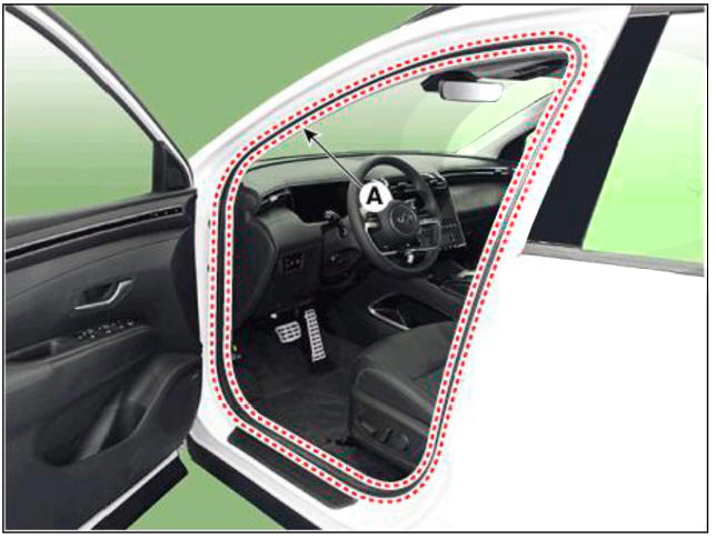
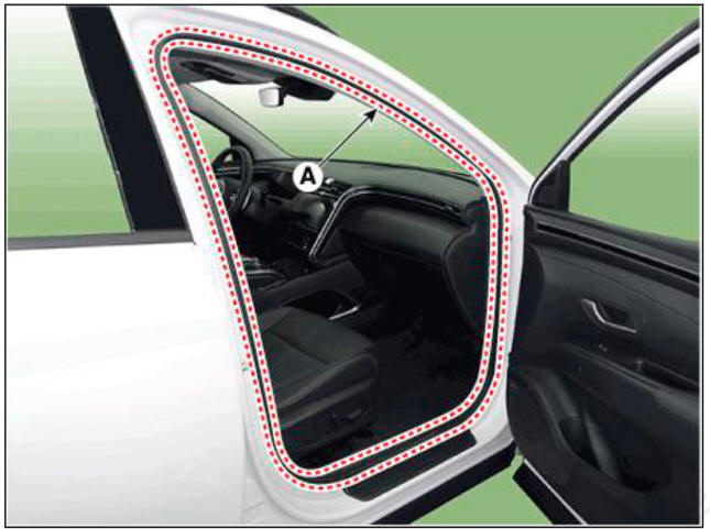
- Remove the front door body side weatherstrip (A).
LH
RH
- Using a screwdriver or remover, remove the crash pad side cover (A).
LH
RH
- To install, reverse removal procedure.
WARNING
Replace any damaged clips (or pin-type retainers).
Replacement
WARNING
- When piying with a flat-tip screwdriver, wrap it with protective tape, and apply protective tape around the related parts, to prevent damage.
- Put on gloves to protect your hands.
WARNING
Take care not to bend or scratch the trim and panels.
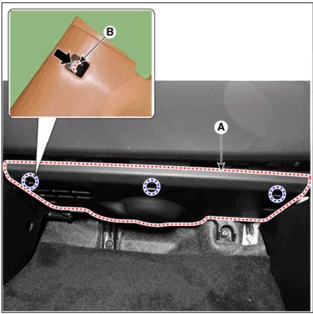
- Press the lock pin (B) and then remove the crash pad under cover (A).
- To install, reverse removal procedure.
READ NEXT:
 Crash pad center panel
Component Location
Crash pad center panel
Replacement
WARNING
When piying with a flat-tip screwdriver, wrap it with
protective tape, and apply protective tape
around the related parts, to prevent damage.
Put on gloves to protec
Main crash pad assembly
Component Location
Main crash pad assembly
Replacement
WARNING
When removing with a flat-tip screwdriver or remover, wrap
protective tape around the tools to prevent damage to
components.
Put on gloves to prevent hand injuries.
Cowl cross bar assembly
Component Location
Cowl cross bar assembly
Replacement
WARNING
When removing with a flat-tip screwdriver or remover, wrap
protective tape around the tools to prevent damage to
components.
Put on gloves to prevent hand injuries.
SEE MORE:
Power Door Locks
Front Door Lock Module Inspection
Inspection
Remove the front door trim.
(Refer to Body - "Front Door Trim")
Disconnect the connectors from the actuator.
Check actuator operation by connecting power and ground according to the
Operation and Leakage Check
Inspection
Brake Booster (A)
(1) Check brake operation by applying the brakes during a test drive. If the
brakes do not work properly, check the brake
booster. Replace the brake booster as an assembly if it does not work properly
or i
Information
- Home
- Hyundai Tucson - Fourth generation (NX4) - (2020-2023) - Owner's Manual
- Hyundai Tucson - Fourth generation (NX4) - (2020-2023) - Workshop Manual
