Hyundai Tucson: Blower - Replacement
- Disconnect the negative (-) battery terminal.
- Recover the refrigerant with a recovery/recycling/charging station.
(Refer to Air conditioning System - "Repari procedures")
- When the engine is cool, drain the engine coolant from the radiator.
(Refer to Engine Mechanical System - "Coolant")
- Remove the cowl top cover.
(Refer to Body (Interior and Exterior) - "Cowl Top Cover")
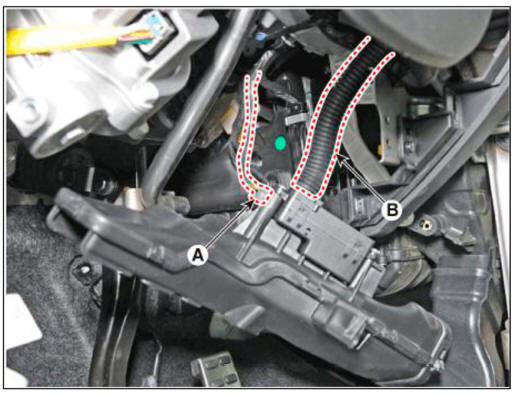
- Loosen the mounting nut and separate the expension valve cover (A).
Tightening torque : 7.8 - 11.8 N.m (0.8 - 1.2 kgf.m, 5.8 - 8.7 lb-ft)
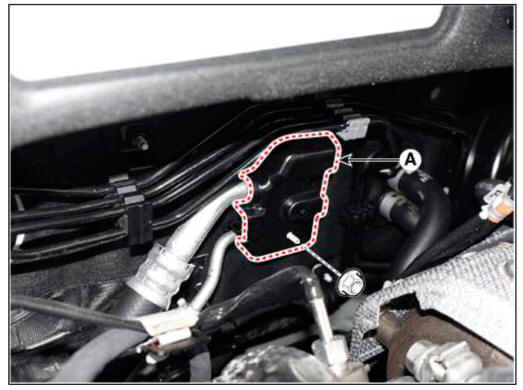
- Loosen the mounting bolts and separate the expension valve (A) from the evaporator core.
Tightening torque : 21.6 - 32.4 N.m (2.2 - 3.3 kgf.m. 15.9 - 23.9 lb-ft)
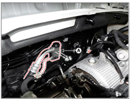
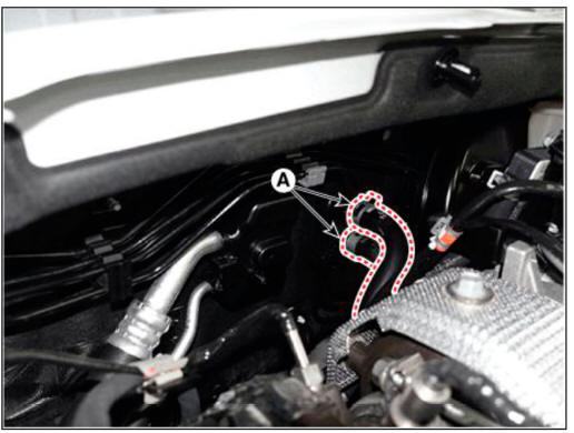
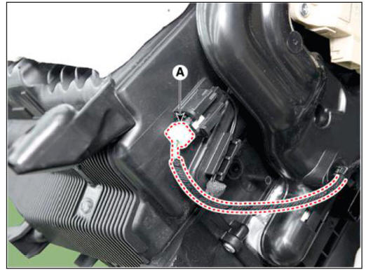
- Separate the heater hose (A).
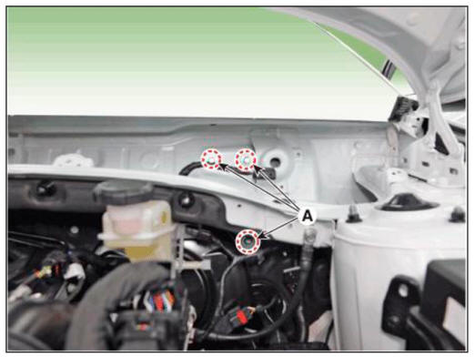
- Loosen the cowl cross bar assembly mounting bolts (A).
Tightening torque : 16.7 - 25.5 N.m (1.7 - 2.6 kgf.m, 12.3 - 18.8 lb-ft)
- Remove the front seat assembly.
(Refer to Body (Interior and Exterior) - "Front Seat Assembly")
- Remove the floor console assembly.
(Refer to Body (Interior and Exterior) - "Floor Console Assembly")
- Remove the front pillar trim.
(Refer to Body (Interior and Exterior) - "Front Pillar Trim")
- Remove the cowl side trim.
(Refer to Body (Interior and Exterior) - "Cowl Side Trim")
- Remove the crash pad lower panel.
(Refer to Body (Interior and Exterior) - "Crash Pad Lower Panel")
- Remove the steering column shroud lower panel.
(Refer to Body (Interior and Exterior) - "Steering Column Shroud Panel")
- Remove the steering wheel.
(Refer to Steering System - "Steering Wheel")
- Remove the multifunction switch.
(Refer to Body Electrical System - "Multifunction Switch")
- Lower the steering column after loosening the mounting bolts.
(Refer to Steering System - "MDPS PowerPack Assembly")
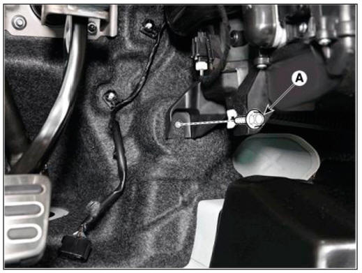
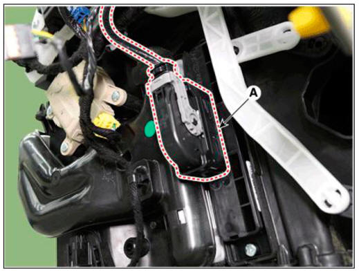
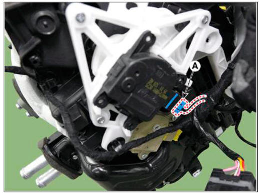
- Loosen the mounting bolt and nut. remove the accelerator pedal module (A).
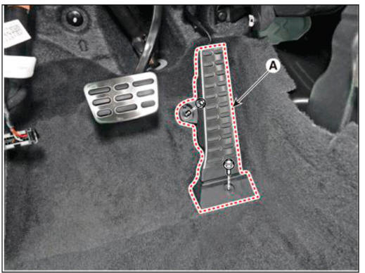
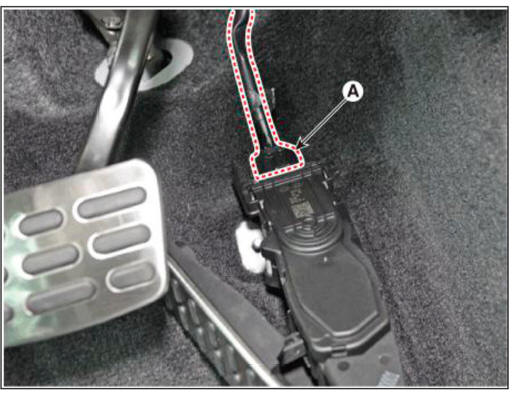
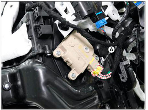
- Press the lock pin, separate the accelerator pedal connector (A).
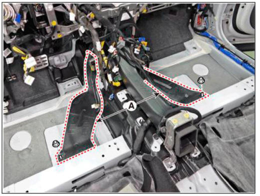
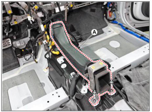
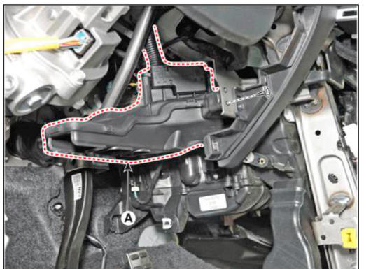
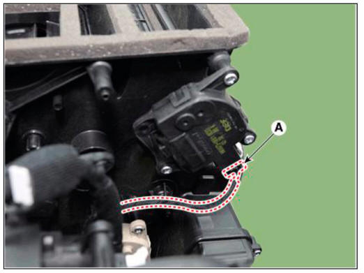
- Remove the rear air duct (B) and then separate the floor carpet (A) backwards.
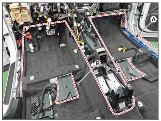
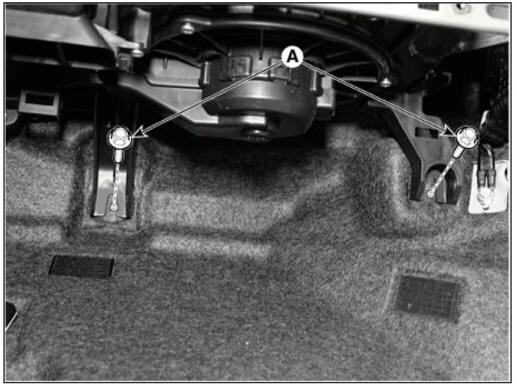
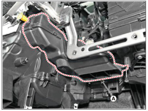
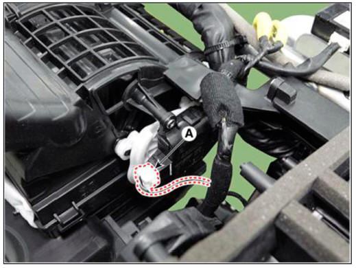
- Loosen the mounting nuts and remove the rear heating duct (A).
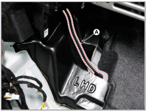
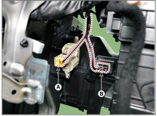
- Loosen the mounting nuts and remove the console duct (A).
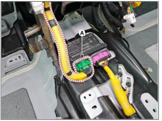
- Disconnect the airbag control modnle(SRSCM) connector (A).
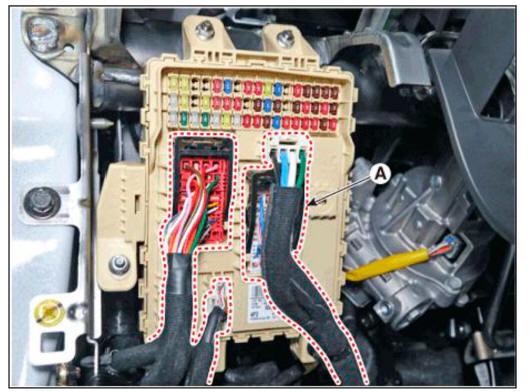
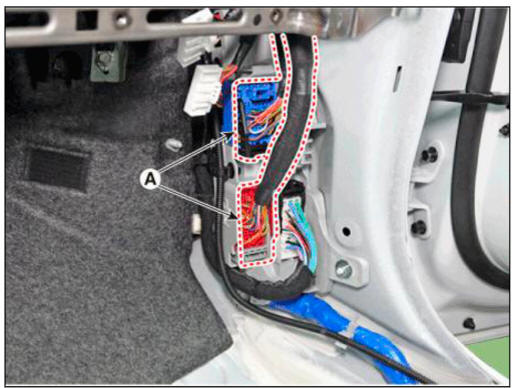
- Disconnect the passenger compartment junction box connectors (A).
- Disconnect the multi box connectors (A).
Driver's
Passenger's
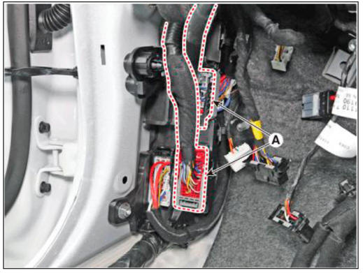
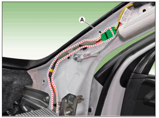
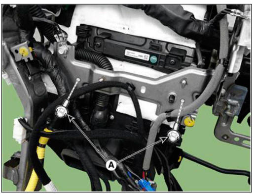
- Disconnect the connector (A) and the mounting wiring fasteners in the front pillar.
Driver's
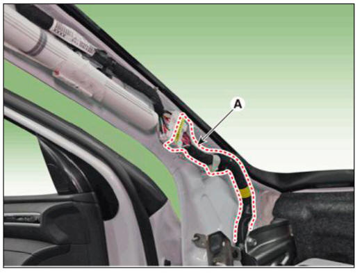
Passenger's
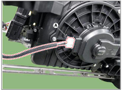
- Remove the drain hose (A).
- Remove the lower mounting bolt of the blower unit.
Tightening torque : 3.9 - 5.9 N.m (0.4 - 0.6 kgf.m , 2.9 - 4.3 lb-ft)
Driver's
Passenger's
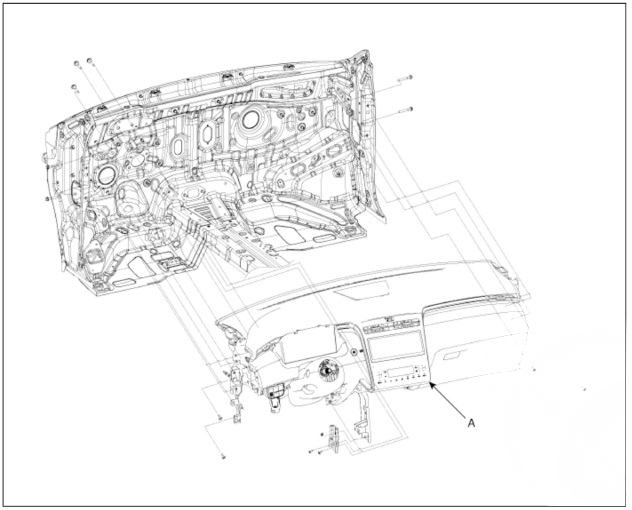
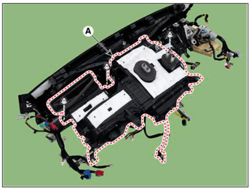
- After loosening the bolts and nuts remove the crash pad and heater & blower unit assembly (A) together.
- Remove the DC DC converter.
(Refer to Engine Electrical System - "DC DC converter")
- Remove the IBU.
(Refer to Body Electrical System - "Integrated Body Control Unit (IBU)")
- Remove the heater control unit.
(Refer to Controller - "Heater Control Unit")
- Remove the shower duct.
LH
(1) Loosen the mounting screw, remove the shower duct (A).
(2) Disconnect the PM sesnor connector (A) and hose (B).
RH
(3) Loosen the mounting screw, remove the shower duct (A).
- Disconnect the heater and blower unit connectors.
(1) Disconnect the PTC heater connector (A).
(2) Disconnect the driver's temperature control actuator connector (A).
(3) Disconnect the mode control actuator connector (A).
(4) Disconnect the auto defogging actuator connector (A).
(5) Disconnect the intake actuator connector (A).
(6) Disconnect the passenger's temperatur actuator connector (A) and power mosfet connector (B).
(7) Disconnect the evaporator sensor connector (A).
(8) Disconnect the blower motor connector (A).
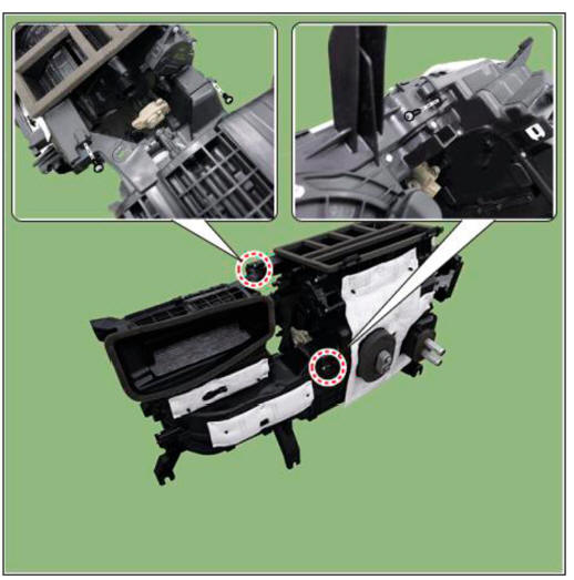
- Loosen the heater & blower unit mounting bolt (A).
Tightening torque : 3.9 - 5.9 N.m (0.4 - 0.6 kgf.m , 2.9 - 4.3 lb-ft)
- Loosen the mounting nuts and remove the heater & blower unit (A) from the crash pad.
Tightening torque : 3.9 - 5.9 N.m (0.4 - 0.6 kgf.m , 2.9 - 4.3 lb-ft)
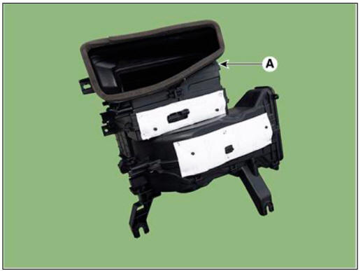
- Loosen the mounting screw and separate the blower unit (A).
Tightening torque : 3.9 - 5.9 N.m (0.4 - 0.6 kgf.m , 2.9 - 4.3 lb-ft)
- Install in the reverse order of removal.
WARNING
- Make sure that each of the assembly components operates properly.
- Replace any damaged clips (or pin-type retainers).
READ NEXT:
 Blower - Inspection
Connect the battery voltage and check the blower motor rotation.
If the blower motor does not operate well, substitute with a known-good
blower motor and check
for proper operation.
Replace the blower motor if it is proved that th
Intake actuator
Components
Intake actuator
Inspection
Turn the ignition switch OFF.
Disconnect the intake actuator connector.
Verify that the intake actuator operates to the fresh air position when
connecting 12V to terminal 3 and grounding ter
Controller
Component
Connector Pin Function
Replacement
Disconnect the negative (-) battery terminal.
Remove the front monitor.
(Refer to Body Electrical System - "Front Monitor")
Remove the heater & AJC control unit (A).
SEE MORE:
Front Muffler
Removal and Installation
Disconnect the battery negative terminal.
Disconnect the oxygen sensor connector (A).
Remove the engine room rear under cover (A).
Tightening torque :
7.8 - 11.8 N.m (0.8 - 1.2 kgf.m, 5.8 - 8.7 lb-ft)
Speed Sensor
Components and Components Location
Control shaft complete
Description
Component location : Control shaft complete is mounted on the top of the
manual transaxle, and
select & shift cable are equipped.
Function : Change the ge
Information
- Home
- Hyundai Tucson - Fourth generation (NX4) - (2020-2023) - Owner's Manual
- Hyundai Tucson - Fourth generation (NX4) - (2020-2023) - Workshop Manual
