Hyundai Tucson: ESC Control unit (HECU) - Adjustment
Hyundai Tucson - Fourth generation (NX4) - (2020-2023) - Workshop Manual / Brake System / ESC (Electronic Stability Control) System / ESC Control unit (HECU) - Adjustment
Adjustment
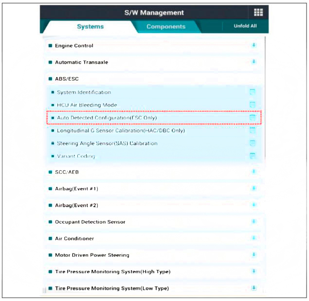
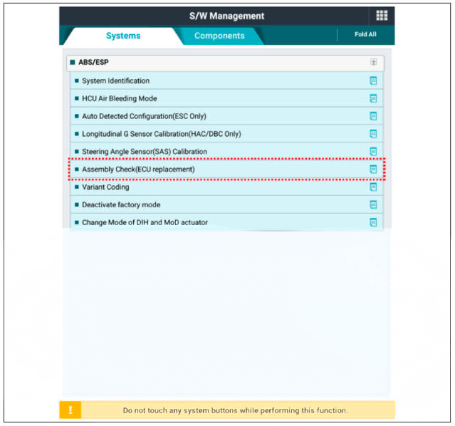
Perform diagnostic procedure by using diagnostic device as shown below :
- Connect self-diagnosis connector (16pins) located under the driver side crash pad to self-diagnosis device, and then torn the self-diagnosis device after key is ON.
- Select the "vehicle model" and "ABS/ESC" on diagnostic tool vehicle selection screen, then select OK.
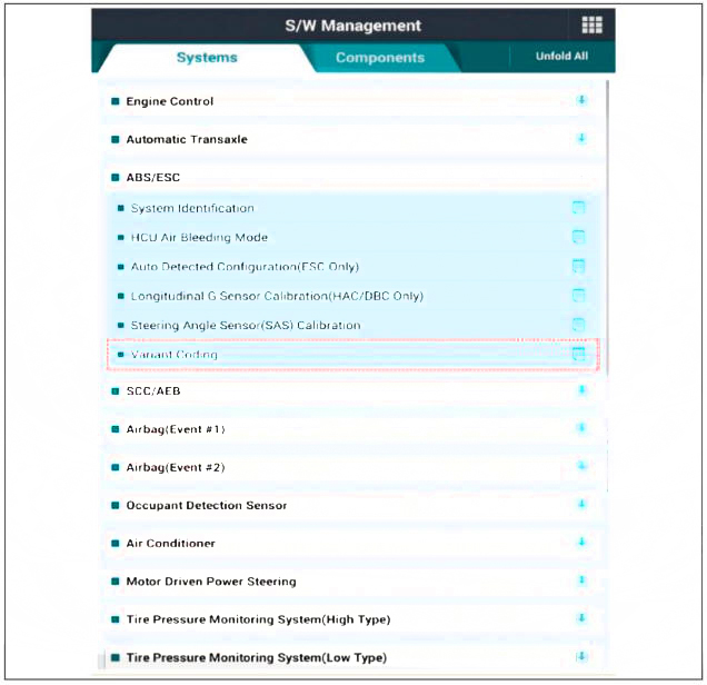
Variant Code Reset
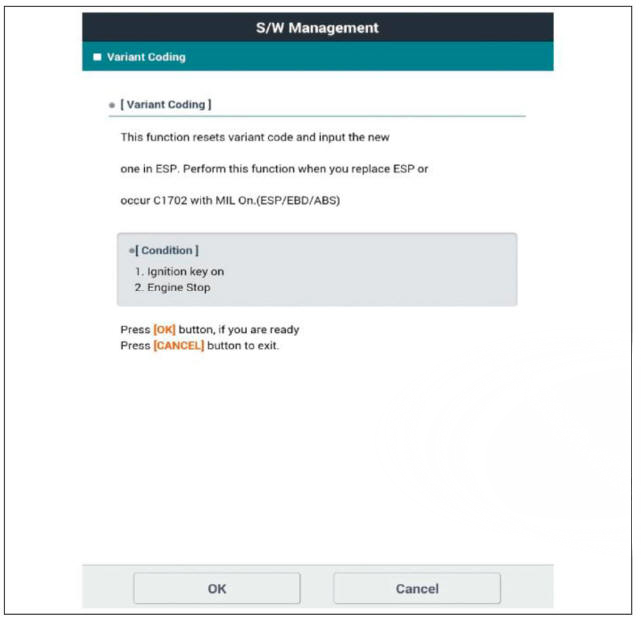
Variant Coding
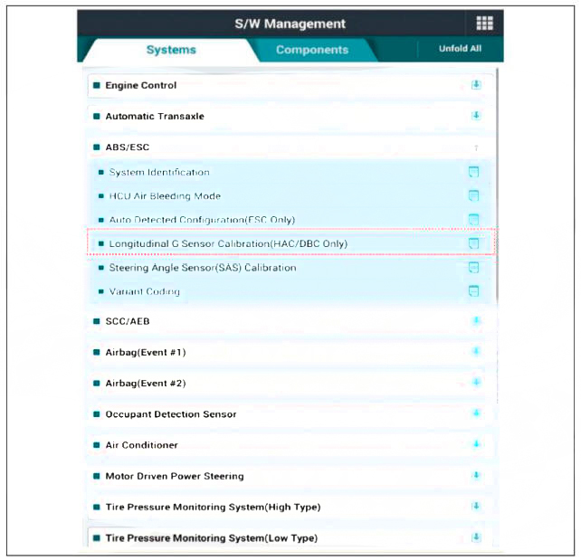
Longitudinal G Sensor Calibration
Assembly Check (ECU replacement)
Description
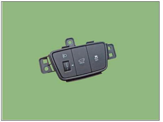
- The ESC OFF switch is for the user to turn off the ESC system.
- The ESC OFF lamp is on when ESC OFF switch is engaged.
Removal
- Disconnect the battery negative ( - ) terminal.
- Remove the crash pad lower panel.
(Refer to Body - "Crash Pad Lower Panel")
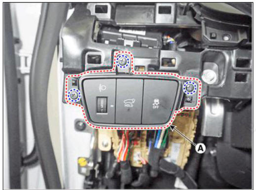
- Remove the screws and remove the ESC OFF switch (A).
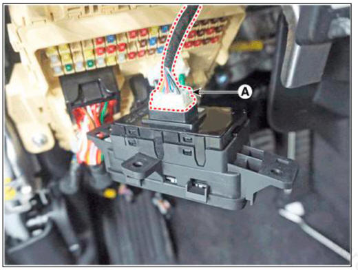
- Remove the ESC OFF switch connector (A) by pressing the locking pin.
Installation
- Install in the reverse order of removal
READ NEXT:
 Front wheel speed sensor/ Front wheel speed sensor connector
Components
Front wheel speed sensor
Front wheel speed sensor connector
Removal
Loosen the wheel nuts slightly.
Raise the vehicle, and make sure it is securely supported.
Remove the front wheel and tire (A) from the front hub.
Rear wheel speed sensor
Components
2WD
Rear wheel speed sensor
4WD
Rear wheel speed sensor
Rear wheel speed sensor- Removal- 2WD
Removal
2WD
Loosen the wheel nuts slightly.
Raise the vehicle, and make sure it is securely supported.
Remove th
Rear wheel speed sensor- Replacement
Replacement
Remove the rear wheel hub bearing assembly.
(Refer to Drivesliaft and Axle - "Rear Hub - Carrier")
Fix the rear hub bearing assembly (A) on the vise.
WARNING
When fixing on the vise, use a cloth not to be damaged
SEE MORE:
Multifunction Switch Inspection
Check for continuity between the terminals in each switch position as
shown below.
Inspection (With Diagnostic Tool)
In the body electrical system, failure can be quickly diagnosed by using
the vehicle diagnostic system (d
Front Bumper - Replacement
Components
Front bumper assembly
Front bumper side bracket
Component Location
Front bumper assembly
Replacement
WARNING
When removing with a flat-tip screwdriver or remover, wrap
protective tape around the tools to
p
Information
- Home
- Hyundai Tucson - Fourth generation (NX4) - (2020-2023) - Owner's Manual
- Hyundai Tucson - Fourth generation (NX4) - (2020-2023) - Workshop Manual
