Hyundai Tucson: Electrical Circuit Inspection Procedure
- Check Open Circuit
- Procedures for Open Circuit
- Continuity Check
- Voltage Check
If an open circuit occurs (as seen in FIG. 1), it can be found by performing Step 2 (Continuity Check Method) or Step 3 (Voltage Check Method) as shown below.
- Continuity Check Method
WARNING
When measuring for resistance, lightly shake the wire harness above and below or from side to side.
Specification (Resistance)
1 or less
→ Normal Circuit
1M
or less
→ Normal Circuit
1M or Higher
→ Open Circuit
or Higher
→ Open Circuit
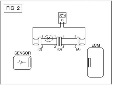
a.Disconnect connectors (A), (C) and measure resistance between connector (A) and (C) as shown in FIG. 2.
In FIG.2. the measured resistance of line 1 and 2 is higher than 1M and below 1
 respectively.
Specifically the open
circuit is line 1 (Line 2 is normal). To find exact break point, check sub line
of line 1 as described in next step.
respectively.
Specifically the open
circuit is line 1 (Line 2 is normal). To find exact break point, check sub line
of line 1 as described in next step.
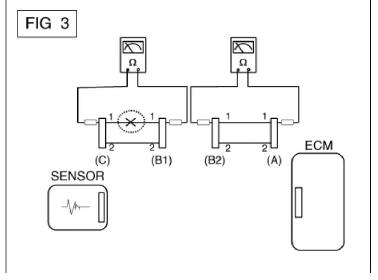
b.Disconnect connector (B), and measure for resistance between connector (C) and (B1) and between (B2) and (A) as shown in FIG. 3.
In this case the measured resistance between connector (C) and (B1) is higher than 1MQ and the open circuit is between terminal 1 of connector (C) and terminal 1 of connector (B1).
- Voltage Check Method
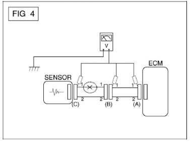
a.With each connector still connected, measure the voltage between the chassis ground and terminal 1 of each connectors (A), (B) and (C) as shown in FIG. 4.
The measured voltage of each connector is 5V, 5V and 0V respectively. So the open circuit is between connector (C) and (B).
Check Short Circuit
- Test Method for Short to Ground Circuit
- Continuity Check with Chassis Ground
If short to ground circuit occurs as shown in FIG. 5, the broken point can be found by performing Step 2 (Continuity Check Method with Chassis Ground) as shown below.
- Continuity Check Method (with Chassis Ground)
WARNING
Lightly shake the wire harness above and below, or from side to side when measuring the resistance.
Specification (Resistance)
1 or less
→ Short to Ground Circuit
1M
or less
→ Short to Ground Circuit
1M or Higher
→ Normal Circuit
or Higher
→ Normal Circuit
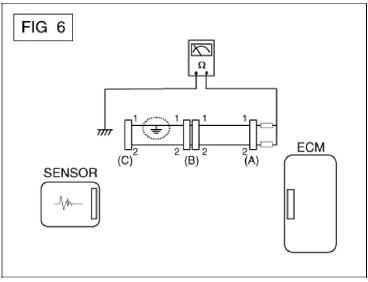
a. Disconnect connectors (A), (C) and measure for resistance between connector (A) and Chassis Ground as shown in FIG. 6.
The measured resistance of line 1 and 2 in this example is below 1
and higher than 1M respectively.
Specifically the
short to ground circuit is line 1 (Line 2 is normal). To find exact broken point,
check the sub line of line 1 as described
in the following step.
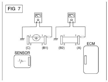
b. Disconnect connector (B), and measure the resistance between connector (A) and chassis ground, and between (B1) and chassis ground as shown in FIG. 7.
The measured resistance between connector (B1) and chassis ground is 1
or less. The short to ground
circuit is
between terminal 1 of connector (C) and terminal 1 of connector (B1).
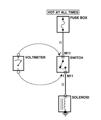
Testing For Voltage Drop
This test checks for voltage drop along a wire, or through a connection orswitch.
- Connect the positive lead of a voltmeter to the end of the wire (or to the side of the connector or switch) closest to the battery.
- Connect the negative lead to the other end of the wire. (or the other side of the connector or switch)
- Operate the circuit.
- The voltmeter will show the difference in voltage between the two points. A difference, or drop of more than 0.1 volts (50mV in 5 V circuits), may indicate a problem. Check the circuit for loose or dirty connections.
READ NEXT:
 Symptom Troubleshooting Guide Chart
Specifications
Fuel Delivery System
Sensors
Manifold Absolute Pressure Sensor (MAPS)
Type : Piezo-Resistive Pressure
Sensor type
Specification
Intake Air Temperature Sensor (IATS)
Type : Termistor type
Specific
Engine Control - Fuel System - Description and Operation
Description
If the Gasoline Engine Control system components (sensors, ECM, injector, etc.)
fail, interruption to the fuel supply or failure
to supply the proper amount of fuel for various engine operating conditions will
result. The following
Components and Components Location
Components Location
Engine Control Module (ECM)
Mass Air Flow Sensor (MAFS)
Manifold Absolute Pressure Sensor (MAPS)
Intake Air Temperature Sensor (IATS)
Boost Pressure Sensor (BPS)
Engine Coolant Temperature Sensor (E
SEE MORE:
Exhaust Emission Control System - Description
Exhaust emissions (CO, HC, NOx) are controlled by a combination of engine
modifications and the
addition of special control components.
Modifications to the combustion chamber, intake manifold, camshaft and ignition
system consist the
basic
Piston Pin - Reassembly
WARNING
Thoroughly clean all parts to assembled.
Before installing the parts, apply fresh engine oil to all
sliding and rotating surfaces.
Always use new gaskets, O-ring and oil seals.
Install the crankshaft position sensor wheel
Information
- Home
- Hyundai Tucson - Fourth generation (NX4) - (2020-2023) - Owner's Manual
- Hyundai Tucson - Fourth generation (NX4) - (2020-2023) - Workshop Manual
